Hi.
My next project is replacing/ upgrading capacitors in a Harman Kardon HK980.
I pretty much have the amplifier boards down as to what to replace, but I am in doubt as to what to replace on the MCU board (schematics attached).
I also plan to replace the power supply caps on the +/- 15volts, 5volts and 12volts lines too.
HARMAN KARDON HK980 230 SM Service Manual download, schematics, eeprom, repair info for electronics experts
I hope some you brilliant guys have some ideas. 🙂
Attachments


Last edited:
Digital control circuits don't have the same demands as those used in linear power amplifiers, DACs or line level audio circuits. You could say it doesn't really matter but there's a benefit in log-term reliability if they are good parts from respected brands and sources. Power supply smoothing and decoupling electrolytics caps are best chosen from high ripple current rated or low ESR type electrolytics. Other than that, decent and popular grades like Panasonic FC and equivalents will be more than good enough for virtually all small electrolytics in the range.
Existing Multi-layer ceramic, disc ceramics, film caps should be fine below 50VDC where smaller value, unpolarized and film caps are used but these don't deteriorate or need replacing like electrolytic caps. Don't waste your time and money replacing those if the processor and its controls are working satisfactorily.
There are many brands and grades of electrolytics out there - always new ones too and lots of Chinese manufacture - even in the popular and respected, high grade brands. I wouldn't get caught up in subjective views about the quality if components in digital control circuits though - that's either a failure issue or imagination running wild.
I am going to use Nichicon FG and ES series in the audio path.
These will be used on the "high power" side:
https://www.mouser.dk/ProductDetail/647-LKS1J123MESC/
Or perhaps these:
https://www.mouser.dk/ProductDetail/661-ESMH630VNN153MA/
Where I am really in doubt, is as to where the audio path is actually impacted in the MCU board?
I know the voltage rails can benefit from better caps, where as lifespan is the main factor, but I am in doubt as to where else to replace caps with better ones?
As an example, this crazy guy 🙂 :
#hk980 | Explore Tumblr Posts and Blogs | Tumgir
He has replaced some caps at the op-amps and volume control, but he also cut a lot of them of without replacing them.
Last edited:
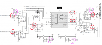
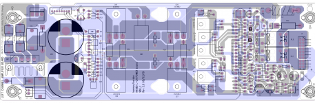
Here is how I see it. Ff you are only going to run the amplifier in "Direct Source" the parts circled in red are to only capacitors in the audio path.
Why they have so many capacitors in the audio path I can't understand. Do they just really want to make sure there will be no DC on the line, in oder to avoid a lawsuit from costumers with blown up speakers?
The capacitors circled in purple are power related and could benefit the op-amps.
Am I completely wrong here?
Attachments
Hi Ian Finch.
Do you know why they opted for bi-polar caps and with lower value at C205/206, but specify polarized caps for the rest of the audio line? Is it a schematic oversight?
Also, just to open Pandora's box, Nichicon Fine Gold vs Panasonic in the same category?
Think you for the help.
Do you know why they opted for bi-polar caps and with lower value at C205/206, but specify polarized caps for the rest of the audio line? Is it a schematic oversight?
Also, just to open Pandora's box, Nichicon Fine Gold vs Panasonic in the same category?
Think you for the help.
Capacitor size in power supplies is a function of the current demand and duty - smoothing and decoupling or bypass are different roles but there are other issues like keeping the inventory manageable and minimising set up costs. A certain value/grade may cost 5c more but if you can save 10c by using the same value/grade in several locations, you win.
The main issue is that for audio signals, polarized electrolytics should only be used where there is a relatively stable DC voltage maintained across them, otherwise the foil electrode becomes polluted and the oxide coating on the other electrode is eroded, inside the cap. The actual audio circuits though, don't have a significant DC charge and basically need to handle the fluctuating polarity of the signal alone, so a special type of construction known as non-polarized, that can handle voltages of either polarity as necessary for audio frequencies at least, is used. These aren't cheap or as good as the best types of film caps but if you want high capacitance in a small space, electrolytics of one type or another, are the only sensible way.
C162 /C23 are decoupling caps for +/-7V power to the volume control board. The requirement is for polarized caps by definition so no-call for non-polars. Neither for C55 which is local decoupling for the +15V supply. Panasonics and competing brands in several low ESR grades will be fine there.
'just an explanation because local lore confuses our terminology here; bi-polar usually refers to the cheap speaker crossover electrolytics that are just 2 standard polarized electrolytics arranged back-to-back. Non-polarized are the real deal by virtue of their manufacture with both electrodes having similar surface coatings.
Anyway, I wouldn't disagree with your cap. grade selections and there aren't a lot of significant choices in a Mouser or Digi-key catalog to discuss anyway. Do they really need replacing though? This is not cheap junk and the lifetime of audio caps of this type are mighty reliable.
Their choice of polarized 100µ / 16 V coupling caps with 3k3 pull-down resistors is in fact odd to say the least. I think several of those caps are mostly intended to safeguard against +/-15 V fed ICs blowing up those on +/-7 V (but they'd only work in one direction). Strictly speaking they are not absolutely necessary... realistically you could ditch C57/58 and 64/65 at least, along with associated R42, 42, 51, 52 plus C163, 164. C53/54 would make much more sense as a bipolar of maybe 10-22µ/35-50 V or so.
I wouldn't go overboard with recapping just yet (chances are, most of it would make zero audible difference at this point), but the 100µ coupling caps going bad seems only a matter of time, even if that probably hasn't come yet after barely more than a decade - 20-25 years in might be a different story. They're also using about 4 of these to RC filter the +/-15 V rails, which seems a bit tight perhaps. See whether you can't find a part of similar footprint but rated at 25 V for C55, 61, 59, 62, 73, 74.
In term of potentially rather more audible improvements, the volume amplifier seems to be needlessly noisy - according to my calculations, output noise should drop by more than 6 dB after adjusting the values of R173/174 and R175/200 from 10k / 27k to more like 2.2k / 5.6k (or 1.6k / 4.3k), respectively. With the following 3k3s (R51/52) + 330p Cs already deleted previously, opamp output loading would still be lighter than stock! More than 6 dB would be a substantial improvement in my book, dropping output noise from only average/mediocre to fairly good territory. Resistor types should be thin-film surface mount, 0603 size is smaller than I like but that's how it is.
Why zener diodes DW6/7 have to run at 7.5 mA when the pass transistors have to deliver ~5 mA each at a beta of at least 100 is anybody's guess as well. I would consider dropping R171/172 from 1k to more like 2k2 and replacing the single 7.5 V zeners with a combination of two 3.6-3.9 V types in series for further reduced noise. (Noise in zener diodes is lowest when the zener effect dominates, which is at the low end at 2.7-3 V. The tempco null around 5.6 V is achieved by balancing zener effect with avalanche effect, with the latter becoming more dominant the higher the voltage. Avalanche effect is far more noisy though.)
Whatever you do, watch out for bad solder joints, H/Ks were notorious for those.
Ian Finch
sgrossklass
It seems like a have a little work ahead of me. Good thing I didn't order components yet.
I do have another question though. I stand in a dilemma of sorts. The Nichicon caps I want to use for the +/-50v is not "new" stock. They have a lower ESR and are cheaper than a new stock Doubler cornell cap.
I understand that the ESR ultimately dictates how much current the cap can deliver and how much heat it would generate, but I just are not sure as to how high an ESR I can get away with before it gets too high?
After some consideration, I do no think I can manage changing the resistors. They are simply too small!
I can manage the removal and bypassing of DC-filter caps and resistors in the audio signal, but soldering small SMDs like that, is simply a catastrophe waiting to happen.
Maybe I can make something with normal resistors and connect their leads correctly at capacitor points on the board?
Damn...
I can manage the removal and bypassing of DC-filter caps and resistors in the audio signal, but soldering small SMDs like that, is simply a catastrophe waiting to happen.
Maybe I can make something with normal resistors and connect their leads correctly at capacitor points on the board?
Damn...
If the SMD resistors are ok just leave them in. You seem performance concerned and worry about ESR without thinking about if lower is always better (it isn't, nor does it always matter).
If you replace an smd resistor with a conventional one in a spot whereever soldering it in you change the position and add the lead parasitics. It's just too much hassle with a bigger change to screw something up than making it "better".
If you replace an smd resistor with a conventional one in a spot whereever soldering it in you change the position and add the lead parasitics. It's just too much hassle with a bigger change to screw something up than making it "better".
In this case, I am pretty much set on what to replace.
All power rail capacitors are going to be replaced by OK quality caps.
All op-amp bypass caps will be replaced with good quality once and at 25v instead of 15v, just to be sure.
Audio path:
C53, 54 will be replaced with bipolar 22u/35v Nichicon ES.
C57, 58, 64, 65, 163, 164 and R42, 43, 51, 52 will be removed and bypassed.
The Tone-circuit will not receive any replacement, because I have no intention of using it.
What about C205, 206? Should I replace those, or perhaps just bypass them?
Can I trust old capacitors sold by Mouser?
OK, I now received the HK980 amplifier, and hole moly it have the loudest physical transformer hum I have ever heard in an amp, Ever...
It sounds like a big industrial transformer. 😛
Could this actually be partly because of "noisy" AC on the power line in this apartment complex?
It sounds like a big industrial transformer. 😛
Could this actually be partly because of "noisy" AC on the power line in this apartment complex?
Last edited:
Well I have replaced the caps on the amplifier boards themselves. Right side board works, the left side I managed to kill. No voltage reading on the TP pins. No bias I guess.
Fuses aren't blown, and nothing popped or smoked when it was turned on.
I just can't figure out where the problem is.
There where some problems with poor quality PCB traces getting lifted from the board at (C9 to Q18, C20 to R42 and C7) but those are fixed with new connections.
Is this a problem with Q18?
I am a bit down over all these problems I have had lately...
Attachments

I have probed some points, and it would seem the Q18 is faulty. It's a BF422 NPN transistor, but it have a 1.036 volt reading between the collector and the emitter, which as far as I understand, it isn't supposed to have.
I guess I killed it when I soldered some pins to it..
I guess I killed it when I soldered some pins to it..
- Home
- Amplifiers
- Solid State
- My next project is replacing/ upgrading capacitors in a Harman Kardon HK980