I like your diagram… its getting rarer and rarer to see “on a napkin” designs such as yours. Well … am older than Dirt itself, so there is that.
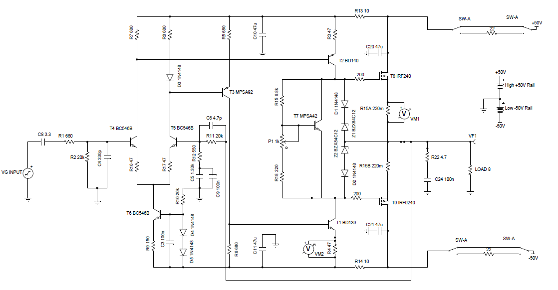
Seems like a fairly straight-forward design: differential symmetric input stage "long tail pair" configuration; constant-current source in common-emitter leg, curious active loading on the collector side. Don't know why it would work, but I can assume it does.
The differential (complimentary) output is then fed to another LTP, but “not really”. First it goes through a couple of emitter followers to reduce load on first LTP pair. Featherweight loading, for all the goodness that comes therein. The now much lower Z of the emitter-followers is fed to the next LTP, which provides gain and all the rest for your MOSFET finals.
The MOSFET finals aren't unconventional, just a pair of complementary polarity cathode-followers pushing-and-pulling the output with only minor global feedback. Current-sharing cathode resistors of 0.22 Ω each, and a couple of reactive-load-overvoltage-shunting ultra-fast diodes to protect the works from the “who knows what kind” of speakers to be attached.
± 45 volt power supply on finals leads to ± 40 volt swings, which if sinusoidally idealized is 40 ÷ 1.414 = 28.3 VRMS. Into 8 Ω, that's [P = E²/R = 28² ÷ 8 = 100 watts]
Nicely done!
Personally, I would have added 2.2 Ω resistors to each of the output overvoltage clamping diodes, to shift away from them (poor things…) the POWER of the shunting operation to something more durable. I also might have included some nonlinear soft-clipping action into the circuit, and definitely a hard current limiter as well. Its so darn easy to blow out the finals with a small short-circuit in the speaker-chain. Frayed wire, you know, "a mistake" that no one saw coming. Even … a fuse would work.
GoatGuy
One thing that you might want to watch out for is the preset resistor in the Vbe multiplier that controls the bias. If, for some reason, the wiper goes open, then there will a tremendous shoot through in the output stage.
Best position it as a variable resistor, making up the bottom half of the divider.
Mike
Best position it as a variable resistor, making up the bottom half of the divider.
Mike
Hi Guys
The BJTs in the diff amp collectors are common-mode current sources. Cordell did this in his 1984 mosfet amp. Since the buffers from the diff amp drive a second diff stage, that second stage has a common-mode signal at its emitter. This signal is fed to the collector load BJTs and greatly improves the common-mode rejection of the circuit.
In Cordell's circuit, the buffers were arranged more intuitively, i.e. they were PNPs. He took the common-mode signal via mixing resistors from the emitters of the EFs rather than from the emitters of the second diff stage.
Suzy J's Little Fish amp used a diff stage(push-pull VAS) to drive its output mosfets, but as with most such designs, there is significant improvement with an actual EF stage between the output of the push-pull VAS and the mosfet gates. It is inexpensive and greatly improves performance and sound.
Have fun
Is it possible to just have one-voltage rails? Say +/- 50V instead of 50 and 45?
Would this change affect anything vital?
Yes. but you will have to drive the gate of these mosfets above the drain by Vth plus Vgs vs Id @Vds saturation if you want to get rail to rail operation under load.
 As for me, I recommend the ol' bootstrap concept for the driver supply but then, everyone has their own ways of doing things
Nice design. I was in the process of experimenting what would happen if I modified a basic Apex front end to drive the same MOSFETs. The simulation seems to look promising and it's a pretty simple design. The addition of the 0.22ohm drain/source resistors really cleaned up the distortion. If you can take a look and let me know what you think that would be great.
Thanks.
Sims are here:
http://www.diyaudio.com/forums/solid-state/164093-100w-ultimate-fidelity-amplifier-720.html
Thanks.
Sims are here:
http://www.diyaudio.com/forums/solid-state/164093-100w-ultimate-fidelity-amplifier-720.html
Veysel, have you a chance to test N version? Does it work?not tested yet.
Hi minek ,n channel version have oscillation and bias problems dont do this.
Too bad, I really like quasi designs.
- Status
- This old topic is closed. If you want to reopen this topic, contact a moderator using the "Report Post" button.
- Home
- Amplifiers
- Solid State
- My new mosfet amplifier (quake)