Did you check out the new nanosharc board on miniDSP site?
It uses a newer generation SHARC processors clocked at 400MHz.
Oh, looks like they lock you into a 96KHz internal sample rate, which means you're basically still stuck around 4000 taps, system wide.
Probably a function of their ASRC or something, maybe it doesn't like dropping from the theoretical maximum of 216KHz all the way to 48KHz, aliasing or something.
Anyway if you want to use 48KHz (let's be honest, most people will) you're stuck with the miniSHARC.
Tho the built in USB audio on the nano is pretty cool.
yes the nanosharc build in usb audio is very good. Now i am searching for a small usb to i2s converter because the mini doesnot have buid in usb. The nanosharc has only 4ch outputs available and only, like you said, 96khz sample rate - a few more taps compared to 96khz minisharc. Even if i used 2 nanosharc's then i will have the outputs i need but only a few taps more and more expensive. I had thoughts about using 3 minisharc's with the opendrc 2x2 plugin and then i would have the 6 outputs i need and each output with 6144 taps at 48khz!! But this solution would be very expensive. Finally i will use one minisharc at 48khz sample rate. At this rate, and using rephase software, i made some simulations and i will need about 1800 taps for the low , 1000 taps for the mid and 700 for the high section. So i will be ok with one minisharc. The only think i would gain using 3 minisharc's is that i could use it at 96khz sample rate. I believe that it is not worth the extra expence. 96k vs 48k is there so much difference?
Yes it is easy to drive the i2s output from the switches i used (74ac11257pw) to more than one sharc inputs. Having for example 3 minisharcs i would not needed the clock buffers (cdcv304pwr) at the minisharc output anymore because each minisharc i2s output will be driven directly to the dac. Of course it will be better to use that clock buffers at the input - after the i2s switch and before the minisharc's.
So in the end i believe that one minisharc is ok for most applications. The problem with it is that it doesn't have any directly usable input (usb, spdif,). On my board i use the spdif input and output but they both need level converters to and from 3,3v.
yes the nanosharc build in usb audio is very good. Now i am searching for a small usb to i2s converter because the mini doesnot have buid in usb. The nanosharc has only 4ch outputs available and only, like you said, 96khz sample rate - a few more taps compared to 96khz minisharc. Even if i used 2 nanosharc's then i will have the outputs i need but only a few taps more and more expensive. I had thoughts about using 3 minisharc's with the opendrc 2x2 plugin and then i would have the 6 outputs i need and each output with 6144 taps at 48khz!! But this solution would be very expensive. Finally i will use one minisharc at 48khz sample rate. At this rate, and using rephase software, i made some simulations and i will need about 1800 taps for the low , 1000 taps for the mid and 700 for the high section. So i will be ok with one minisharc. The only think i would gain using 3 minisharc's is that i could use it at 96khz sample rate. I believe that it is not worth the extra expence. 96k vs 48k is there so much difference?
Yes it is easy to drive the i2s output from the switches i used (74ac11257pw) to more than one sharc inputs. Having for example 3 minisharcs i would not needed the clock buffers (cdcv304pwr) at the minisharc output anymore because each minisharc i2s output will be driven directly to the dac. Of course it will be better to use that clock buffers at the input - after the i2s switch and before the minisharc's.
So in the end i believe that one minisharc is ok for most applications. The problem with it is that it doesn't have any directly usable input (usb, spdif,). On my board i use the spdif input and output but they both need level converters to and from 3,3v.
A heads up, if you use different filter lengths on each output channel, you will have to do phase correction on the mid and high pass channels, if I recall correctly, to get the slopes to complement correctly. Some experimentation with square waves and a multichannel oscilloscope will be in order, methinks.
yes different taps count=different delay. This delay differences must be added to the mid and high channels.
Could someone tell me the differences between those:
use only FIR vs. use combination of IIR for the filters and drivers equalisations and FIR for phase corrections. As i can see from simulations the second solution needs fewer taps for the FIR section. Where are the drawbacks?
Could someone tell me the differences between those:
use only FIR vs. use combination of IIR for the filters and drivers equalisations and FIR for phase corrections. As i can see from simulations the second solution needs fewer taps for the FIR section. Where are the drawbacks?
yes different taps count=different delay. This delay differences must be added to the mid and high channels.
Could someone tell me the differences between those:
use only FIR vs. use combination of IIR for the filters and drivers equalisations and FIR for phase corrections. As i can see from simulations the second solution needs fewer taps for the FIR section. Where are the drawbacks?
So don't confuse delay correction with phase correction in this context.
If you are wanting to correct for physical distance differences, delay is what you want, which is a buffer-based delay mechanism I believe.
FIR phase correction let's you adjust phase of specific ranges of frequencies throughout the filter, plus and minus 180 degrees or so.
hello to everyone,
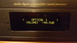
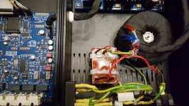
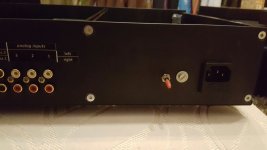
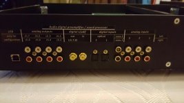
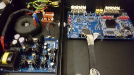
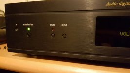
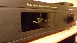
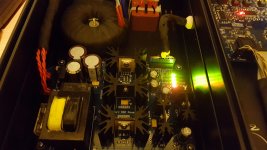
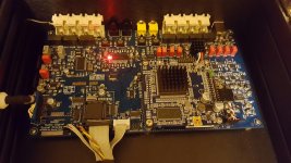
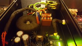
finally i managed to finish the preamplifier. On the photos you can see the finished unit. I have checked the functionality and everything seems to work fine. I have not connected it yet to my system. At this point i must ask for little help. I have already designed a few active crossovers (analog) for my 3way spreakers. I designed them by measuring (umik mic) and using software on pc and a minidsp 2x4 for testing the results and then designing the analog version of it. Everything went well and the system sounds and measures fine.
Now i wanna try to use this digital preamplifier-crossover for the same purpose. This unit will replace my analog preamplifier and active crossover.
How do you suggest to setup this unit? By using the same filters (as the analog one) as IIR filters together with FIR only for phase linearization? Or it is better to design it completelly using FIR only? Or some other configurations?
What do you suggest?
Attachments
Last edited:
Uh, where did you get that enclosure??? It's amazing!
If you are trying to do aggressive filter Q's with a 3 way stereo system, you'll need to be careful with how many taps you eat up on the low frequency filters to be sure you have enough to go around.
I personally can never advocate using analog filters on a SHARC DSP, it's just wrong. 😛
If you are trying to do aggressive filter Q's with a 3 way stereo system, you'll need to be careful with how many taps you eat up on the low frequency filters to be sure you have enough to go around.
I personally can never advocate using analog filters on a SHARC DSP, it's just wrong. 😛
As soon as you propose a stereo 4-way crossover equipped with a SHARC CPU, most people will visualize their next home HIFI system this way, quite inexpensive :
- a single 30 cm long-throw fiberglass bass driver in a closed box covering 20 Hz to 120 Hz (Kenford SBX3040) - two of them at the bottom of your enclosure in case you listen quite loud - four of them if you listen extremely loud
- a single 16 cm polypro midbass driver in a closed box covering 120 Hz to 340 Hz (Rockwood NY6510)
- two 5 cm aluminium medium drivers in a closed box covering 340 Hz to 3400 Hz (Fountek FR58EX), d'Appolito with the tweeter
- a miniature neodyme dome tweeter (Dayton ND25) covering 3,400 Hz to 15,000 Hz, located between the two medium drivers, as close as possible to the medium drivers, the tweeter coming at the same height as the listener's ears, that's sitting in a sofa.
The medium driver center, to the tweeter center distance shall measure 7 cm, or less. Such distance needs to be compared to half the sound wavelength in air at 3400 Hz, which is 5 cm. Thus, even if the second medium driver was not there, the interference pattern between the medium driver and the tweeter is not going to exhibit the kind of irregularities that can render a multiway speaker setup very complicated, and full of compromise. In our case, thanks to the second medium driver that's there for creating a virtual medium acoustic center that's aligned with the tweeter acoustic center (d'Appolito principle), the interference pattern between the medium drivers and the tweeter will remain unnoticeable, guaranteeing a wide and regular radiation pattern, a flat frequency response from all listening angles, in all directions. The walls, floor and and ceiling will reverberate a high quality, natural sound. This is of paramount importance, as 80% of the sound that you perceive while sitting in a concert hall is reverberated sound. On can guess that more than 50% of the sound that you perceive wile sitting in a sofa, is reverberated sound, because while facing a speaker, your ears are not facing such speaker.
Ideally speaking, the medium phase shall follow the tweeter phase, from 1700 Hz to 6800 Hz. That's actually feasible. Linkwitz-Riley filters can guarantee such phasing. In Linkwitz-Riley filters, the phase of the lowpass filter that's feeding the medium driver, is forced to precisely follow the phase of the highpass filter that's feeding the tweeter. An easy Linkwitz-Riley lowpass filter is implemented by cascading two 2nd-order Butterworth lowpass filters, acting together for setting the 3400 Hz at -6 dB. At 3400 Hz, the phase is down by 180 degree. An easy Linkwitz-Riley highpass filter is implemented by cascading two 2nd-order Butterworth highpass filters. At 3400 Hz, the phase is up by 180 degree, but wait a minute, in a trigonometric circle, who can make a difference between plus 180 degree and minus 180 degree? Such naughty trick is only valid for a pure sine signal. Thus, provided one is thinking in terms of pure sine signal, the lowpass filtered medium driver phase, appears to match the highpass filtered tweeter phase. But this is an an illusion, as in reality, physically, there is a time difference equal to one period at 3400 Hz, explaining the illusion.
The computing load that's imposed for implementing the above Linkwitz-Riley filter at 3400 Hz can be considered as insignificant, very low, speaking about a SHARC CPU where each 2nd-order Butterworth filter can be implemented using a single IIR Biquad filter consuming 5 machine cycles or so.
Left medium : 2 Biquads
Left tweeter : 2 Biquads
Right medium : 2 Biquads
Right tweeter : 2 Biquads
Total required : 8 Biquads. Say 40 machine cycles or so.
One can apply the same protocol at 120 Hz for the woofer / midbass crossover, and at 340 Hz for the midbass / medium crossover.
Thus, 120 machine cycles or so.
Now consider a SHARC CPU clocked at 100 MHz, each machine cycle taking 10 ns. The required 120 machine cycles will take 1.2 µs execute.
Now consider a 96 kHz audio sampling frequency, which is equivalent to 10.4 µs period. The SHARC CPU will get used at 1.2 / 10.4 = less than 12%.
A CPU like a SHARC CPU would be better exploited, taking advantage of FIR filters, also named "transversal" filters. FIR filters allow to specify a gain curve that's the same as a double-Butterworth filter, along with a phase curve that's no longer lagging or advancing like and analog or digital IIR Biquad filter, but a phase curve that's on purpose, linearly increasing with frequency, hence equivalent to adding a certain delay. FIR filters specified this way, are named "linear phase" FIR filters.
The beauty of FIR filters in crossovers is that one single FIR filter can at the same time, a) impose the global lowpass and/or highpass pattern, and b) impose the numerous tiny amplitude corrections that are required for ironing out the small hills and valleys that most speaker drivers exhibit in their native response curves.
Practically, for setting up the required FIR filter, you need to compare the desired filtered amplitude response curve (aka filtered like you want) against the actual unfiltered driver amplitude response curve. The difference curve is your target FIR filter amplitude curve. Say you base on a 1024-tap FFT analyzer. It'll deliver 512 frequency bands, acting as a frame enabling to tell the required filter gain and phase for each band. Say the sampling frequency is 96 kHz. Each frequency band will measure 188 Hz in bandwidth. This means that such FIR filter has the capacity to re-shape the response curve at will, with a resolution of 188 Hz. In our case, speaking of a crossover operating at 3400 Hz, this looks ideal. Imagine the medium driver, having its response curve that's starting from 340 Hz, getting re-shaped and flattened with a resolution of 188 Hz, then getting lowpass filtered at 3400 Hz. Imagine the tweeter, getting highpass filtered at 3400 Hz, along with his frequency response getting also re-shaped and flattened with a resolution of 188 Hz, till 20 kHz or so.
And, cherry of the pie, no more phase distortion above 340 Hz. Because the 3400 Hz crossover is phase-linear.
Such method is easy to implement. Remember the 512 frequency bands, acting as a frame enabling to tell the required filter gain and phase for each band. Do an inverse FFT of this. What do you get as output? Answer: 1024 values materializing the impulse response of the filter. In other words: the 1024 FIR filter coefficients. So trivial.
A SHARC CPU is specifically designed for efficiently executing a FIR filter, to the point that a 1024 FIR filter does execute in 1024 machine cycles.
Here assuming that each machine cycle takes 10 ns, the FIR filter will execute in 10.24 µs.
Let's compare those 10.24 µs is with the 10.40 µs maximum execution time that's imposed by the 96 kHz sampling frequency. With some luck, it may indeed work, but this is only for one FIR filter. And we require four :
Left medium : one 1024-tap FIR filter
Left tweeter : one 1024-tap FIR filter
Right medium : one 1024-tap FIR filter
Right tweeter : one 1024-tap FIR filter
Quite annoying. It seems that we require a SHARC CPU at least 4 times more powerful than our estimate. Is it a 400 MHz SHARC CPU that's soldered on your board?
In case there is, we can truncate the FIR filters, leaving out their last 224 taps, for only computing their first 800 first taps.
This way the execution of the four FIR filters only takes 8 µs, leaving almost 2 µs (800 machine cycles) for implementing the rest of the crossover (left and right woofer filters, and left and right midbass filters) using IIR Biquad filters consuming very little computing power. Which means that under 340 Hz, the filtering will consist of IIR Biquad filters.
In such frequency range, below 340 Hz, because of being in presence of a digital crossover, we can exploit IIR Biquad filters, not anymore for building Linkwitz-Riley crossovers emulating analog crossovers hence being not exact what's regarding the global phase, but for building Lipshitz-Vanderkooy crossovers having the advantage of being exact what's regarding the global phase.
- a Lipshitz-Vanderkooy crossover generating a lowpass at 120 Hz for the woofer, and a highpass at 120 Hz for the midbass
- a Lipshitz-Vanderkooy crossover generating a lowpass at 340 Hz for the midbass, and a highpass at 340 Hz for medium driver
Please note, the "textbook" 4th-order Lipshitz-Vanderkooy crossover is a subtractive crossover basing on a 4th-order IIR Biquad Butterworth lowpass filter (delivering the bass signal), a delay line, and a subtractor (generating the treble signal). It is thus slightly faster to execute than a 4th-order Linkwitz-Riley crossover, as the delay line and subtractor are faster to execute than the double IIR Biquad Butterworth highpass that the Linkwitz-Riley requires.
Such "textbook" 4th-order Lipshitz-Vanderkooy provides a 4th-order Butterworth lowpass (for the bass signal) and a subtracted highpass that's roughly, a 3rd-order (for the treble signal). The big advantage of the Lipshitz-Vanderkooy is that it respects the global phase. It doesn't introduce any phase distortion. This is much better than the Linkwitz-Riley. A small disadvantage of the Lipshitz-Vanderkooy is that it causes a slight phase mismatch between the bass signal and treble signal, generally considered as negligible. This is caused by the propagation delay increase at the vicinity of corner frequency of the Butterworth lowpass.
There are "non-texbook" aka "tweaked" Lipshitz-Vanderkooy filters basing on a 4th-order Bessel lowpass instead of a 4th-Butterworth lopass, ensuring minimal phase mismatch between the bass signal and the treble signal as now the bass signal exhibits a flat propagation delay before attenuating. The delay line must be adjusted with great precision for ensuring that the highpass output, delivers something better than a 2nd-order highpass. Indeed, in case the delay line is adjusted for coinciding with the group delay of the Bessel lowpass filter, the highpass section provides a 2nd-order highpass, which is judged as providing an insufficient protection against powerful bass content. Starting from such point, by finely and progressively de-tuning the delay line, you will see an interesting compromise developing, delivering a highpass slope that can reach a pseudo 4th-order close to the crossover frequency (good protection against powerful bass content), in exchange of a little (thus not harmful) phase mismatch between the bass and the treble output. All this, in the context of no global phase distortion, due to the subtractive nature of such crossover.
This is the way I roughly see the use of the SHARC CPU, in the context of a digital stereo 4-way crossover.
As you can see, there is never question of "compensating the global phase" because in FIR filters (requiring a lot of computing power) and also in Lipshitz-Vanderkooy crossovers (only requiring a few IIR Biquad filters plus a delay line), the global phase gets optimally dealt with, inside each filter.
Please note, I agree that for the ones not having enough time for reading and understanding what's above, it sounds far less complicated to always rely on Linkwitz-Riley crossovers basing on IIR Biquad filters, emulating analog filters. Which are under-exploiting the SHARC CPU possibilities in a very disappointing way. And like you suggested, some satisfaction can develop after counting how much computing power remains for implementing a global gain / phase equalizer, say a 2048-tap FIR filter at the left channel input, and the same 2048-tap FIR filter at the right channel input. Providing a 94 Hz resolution. We get thus a fair chance of flattening the phase bump at 340 Hz, and the phase bump at 3400 Hz. Only leaving the phase bump at 120 Hz.
Starting from this, as an option, one could propose a 120 Hz "tweaked" 4th-order IIR Biquad Lipshitz-Vanderkooy crossover, instead of the 120 Hz 4th-order IIR Biquad Linkwitz-Riley.
The disadvantage of such conception is that regarding the 3400 Hz crossover, by using a IIR Biquad Linkwitz-Riley crossover instead of 800-tap FIR filter crossover, the user won't realize that his medium driver is far from ideal at 3400 Hz, possibly plagued by some resonance, and also that his miniaturized neodyme tweeter is far from ideal at 3400 Hz, quite close to its native highpass slope. You may help the user getting aware of this, by motivating him to measure the unfiltered response curves (in gain and in phase) before attempting to setup the IIR Biquad Linkwitz-Riley crossover. Anyway, doing so, you shall add a few extra IIR Biquad filters at the user's disposition, hoping he has the skills for using them for flattening the drivers response curves (in gain and in phase), even before applying the IIR Biquad Linkwitz-Riley crossover. It is there that the user will realize that each time he tries to flatten the gain around a given frequency, using some extra IIR Biquad filter as controlled notch, or as baffle step compensation, or anything else, that such action is always causing a bump in the phase, making the gain and phase "idealization" of a speaker driver, very problematic. It is at such stage, that the user may feel betrayed, robbed, in case there is no FIR filter approach available, not as "global gain and phase equalization", but as advanced filter technology to be used for the 3400 Hz crossover, applied to the d'Appolito medium driver(s), and applied to the tweeter.
When measuring the gain and the phase a bare speaker driver, or a filtered speaker driver that's mounted inside an enclosure, I will always rely on a dual channel FFT analyzer running on a Windows PC like SpectraLab 4.32, developed in the mid nineties by skilled people gravitating around HP. Such dual channel FFT analyzer has two inputs, not related to the idea of stereo, but related to the idea of being able to explicitly measuring the phase, without guessing whatsoever. One input channel sees the reference signal, actually the pink noise voltage (or 1/10th of it) that's applied to the speaker driver. The other input channel sees the voltage that's coming from a measuring microphone. The dual channel FFT analyzer shall use a 96 kHz sampling frequency, doing a 2048-samples FFT on both input channels. The two FFT results get compared both in amplitude and in phase, and this enables graphing both the gain and the phase explicitly, every 94 Hz or so till 48,000 Hz without guessing anything.
This is the way everybody used to work. There was thus a "loopback" cable required, going from the speaker terminals, to one of the FFT analyzer inputs.
Recent popular FFT analyzers running on a Windows PC, like Arta, tend to promote the idea that dual channel FFT analyzers are things of the past. In the Arta user manual, there are many different modalities for getting a gain and phase curve, including some that not relying on a "loopback" cable.
Through Arta user manual, there is question of guessing the phase from the gain. Which is mathematically feasible, at the condition that the system that's measured is "minimum phase". Unfortunately, a Linkwitz-Riley crossover is not "minimum phase", as when you sum the bass and treble outputs, the global phase shows heavily distorted.
Through Arta manual, it is not clear where and when Arta folds back to a digital loopback, in case the user doesn't provide a proper loopback cable. Such digital loopback is by far inferior to a proper loopback cable, as with the digital loopback, the DAC and ADC transfer functions of the sound card don't get neutralized (considering here that both DACs exhibit the same transfer function and delay, and that both ADCs exhibit the same transfer function and delay, which is true to 0.1 dB and 1 degree).
With the digital loopback, the PC software must compensate the ADC delay and DAC delay of the measured channel, to be indicated by the user, graphically.
Through Arta user manual, there is also question of the "Farina" method that's able to graph the individual harmonic distortion levels (k2, k3, k4), along with what seems to be a phase curve, plus of course the gain curve, all this without requiring a "loopback" cable. I need to know if is the particular non-statistical nature of the test signal (sort of frequency chirps) that's enabling Arta to graphe a phase in the "farina" method, without requiring a loopback cable, or if in such case, like in other cases, a) the phase gets graphed because of Arta folding back to a digital loopback or b) the phase gets graphed by guessing it from the gain curve, in the context of a supposedly "minimum phase" system.
What's described above looks deterrent for any non-specialist. This has as effect, that as soon as there is question of measuring a gain along with a phase, I mean really measuring a phase instead of guessing a phase, or instead of guessing some DAC and ADC latency by manually pointing the beginning of an impulse response, most non-specialist people will run away.
For such reason, I tend to consider that a good digital crossover should provide two wires, a reference signal wire, and a measured signal wire, for helping people realize that all what's required for measuring a gain and a phase, is mostly there, provided by the crossover.
Up to you to see if this is feasible. I don't mean the digital crossover to embed a FFT analyzer, graphic display and user interface. I only mean motivating the user to hook, not only a measurement mike, but also a reference signal wire. Which means, the digital crossover to generate the test signal, in our case a pink noise. And possibly, rely on SpectraLab 4.32 (demo mode, all options enabled), or preferably rely on some straightforward homemade 2-channel FFT analyzer, running on a Windows PC, for displaying the gain and phase curves, and visualizing what's happening when the user enables the Linkwitz-Riley crossover, plus some extra IIR Biquad filters for idealizing the drivers before applying the Linkwitz-Riley crossover.
Later on, a "FIR design" PC application could squat the 2-channel FFT analyzer, for allowing the user to practice FIR filters and crossovers built using FIR filters. On the Windows PC, the user would select a target gain curve and target phase curve (or delay), that gets real-time compared to the actual gain and phase of the bare driver. As example, the user would specify "Fs 96 kHz" "FFT 2048 samples", and "high pass -6dB @ 340Hz 4th-order Butterworth linear phase", and "lowpass -6dB @ 3400 Hz 4th-order Butterworth linear phase". This way whatever the gain and phase of the unfiltered medium driver, the PC can compute the required FIR filter. As soon as the FIR filter coefficients are computed by the Windows PC, they get sent to the digital crossover using USB (or a serial-to-USB bridge). The crossover then enables the FIR filter, and tells this to the Windows PC, in order the Windows PC to display the actual filtered output, without confusing it with a bare speaker output. Ideally speaking, the Windows PC should then be able to appreciate the difference between the realized transfer function, and the target transfer function, for finely adjusting the FIR filter coefficients in some incremental way.
This way, after one or two minutes of incrementally improving the realized transfer function, it is hoped that any speaker driver transfer function gets conformed to the 340 Hz to 3400 Hz target transfer function, within 1 decibel and 10 degree or so, automatically, without requiring any user intervention, apart from specifying the target transfer function.
This way, the digital crossover gets never asked to perform a FFT, or an inverse FFT, or some averaging on this. Only the Windows PC does this. The digital crossover only receives FIR coefficients from time to time from the Windows PC, using USB. Not very different from receiving IIR Biquad coefficients indeed.
Yes you can! You'll make digital crossovers great again!
By the way, I would prefer operating at the genuine sampling frequency, in other words 44.1 kHz when reading a CD (possibly dematerialized), and 48 kHz when reading a DVD or BluRay, and 96 kHz when reading audiophile content that got produced using 96 kHz gear.
Thus, both the Windows PC (FFT analyzer) and the digital crossover, should adapt.
Last edited:
Doing FIR filters, the MiniSHARC is limited to 2048 taps max per channel and for 48kHz processing a maximum of 9600 taps total. With 96kHz taps, you are limited to max 3400 taps total, but still a max of 2048 taps for a single channel.
When doing LF corrections below 100Hz, 2048 taps is not sufficient to get an accurate curve, while much less is needed for higher frequencies. Doing test eq and calculations with rePhase will quickly show you the problems here.
I have an OpenDRC DA-8, that uses the same MiniSHARC board, and I've tried to use 2048 for the woofer channels, 1024 for the mids and 650 for the tweeters. It will still mess up heavy-handed corrections in the LF band.
Now, if you take a look at what Bruno Putzey at Hypex writes on loudspeaker correction, most of the loudspeaker correction needed is minimum phase. This means that when you correct frequency problems with a IIR filter, the phase problems will fall in line, too.
Therefore, what I suggest is using REW to make IIR EQ with biquads. Then remeasure, and do fine adjustments with FIR. If you want higher order crossovers like 60dB/oct, you need to do those in FIR as well.
Stephs method above is totally unfeasible with the MiniSHARC board and MiniDSP software. And by the way, the plugin is limited to either 48 or 96kHz processing.
Johan-Kr
thank you all for your answers. So if i understand right, it is better (that is my conclusion from what i have read so far about digital filtering) to use IIR for the driver eq and for HPF or LPF filters and then use the FIR only for phase corrections? Or use the IIR for Hpf and Lpf and then FIR for driver eq and phase correction. If there are enough taps available it is better to use only FIR filters? I have made a simulations using rephase and the available taps is enough for me (48k plugin).
I am thinking to design the crossover using IIR filters (using lspcad for example) then using rephase for the IIR filter phase linearization. Is this method correct?
I am thinking to design the crossover using IIR filters (using lspcad for example) then using rephase for the IIR filter phase linearization. Is this method correct?
Uh, where did you get that enclosure??? It's amazing!
If you are trying to do aggressive filter Q's with a 3 way stereo system, you'll need to be careful with how many taps you eat up on the low frequency filters to be sure you have enough to go around.
I personally can never advocate using analog filters on a SHARC DSP, it's just wrong. 😛
the enclosure is custom made from Modushop by Hi-Fi 2000 | Contenitori per Elettronica | Electronic Enclosures | Hi Fi Chassis. They have very good looking enclosures. I have ordered from them before but this is first time i use their customization service whith is very good.🙂
If you want to do steep filters, you need to/should use FIR.
Do most of the driver EQ with IIR, and then fine tune with FIR. Note that you cannot EQ everything.
Johan-Kr
Do most of the driver EQ with IIR, and then fine tune with FIR. Note that you cannot EQ everything.
Johan-Kr
For sure it is correct and therefore, instead of reinventing the wheel, you shall buy a $205 miniDSP 2 x 4 HD featuring a ADSP21489 400MHz Sharc DSP floating point engine, and learn from this.I am thinking to design the crossover using IIR filters (using lspcad for example) then using rephase for the IIR filter phase linearization. Is this method correct?
IMO, you are capable of designing a PCB hosting a high quality ASRC chip at the input (convert everything to 96 kHz), a high quality 96 kHz (and 96 kHz x 128) clock generator, three ADSP21489 400MHz Sharc DSP chips each featuring 5 Mbits of on-chip RAM, and one STM32F4 microcontroller doing the housekeeping like allowing the three ADSP chips to communicate with a Windows PC or macOS PC using a slow speed USB at 1 Mbit/s for transmitting commands, reports, FIR filters coefficient lists, and IIR filters coefficient lists.
Each ADSP21489 400MHz Sharc DSP is able to execute two 2000-tap FIR filters (one for the left channel, the other for the right channel) at 96 kHz. You can view this in the context of a forward DFT covering N = 2000 audio samples in time domain as input, that's delivering as output (N/2) + 1 = 1001 real values in frequency domain, and also 1001 imaginary values in frequency domain. Such 2000-tap filter is sculpting your frequency response and phase response like a sophisticated 1001-band equalizer :
- 1st frequency from DC to 24 Hz (24 Hz bandwidth)
- 2nd frequency band 24 Hz to 70 Hz (48 Hz bandwidth)
- 3rd frequency band 70 Hz to 118 Hz (48 Hz bandwidth again)
- etc...
- 1000th frequency band 47,928 Hz to 47,976 Hz (48 Hz bandwidth)
- 1001th frequency band (last one) 47,976 Hz to 48,000 Hz (24 Hz bandwidth)
Thus, by choosing a closed enclosure or a bass-reflex enclosure for the bass range, featuring one, two or more 30 cm woofers being cut at 340 Hz (-6 dB point), one can expect the 340 Hz lowpass FIR filter for the woofer, and the 340 Hz highpass FIR filter for the medium driver, to be adequately smooth and precise, as those filters exhibit a 48 Hz frequency resolution in the audio band.
Concerning the very fine equalization in the deep bass, between 20 Hz and something like 120 Hz, several IIR Biquad filters shall be used. I'm saying equalization. This is different from crossing over.
What's concerning the 3400 Hz crossover, the 2000-tap FIR filter looks overkill, until you realize it comes for free. Look the medium driver. One can specify a single FIR filter for implementing the highpass that's required at 340 Hz, and the lowpass that's required at 3400 Hz, and as consequence this will also iron out any bump showing between 340 Hz and 3400 Hz.
To be honest, looking to the tweeter driver, one can say that the 2000-tap FIR filter looks overkill, because it would suffice a 500-tap FIR filter featuring a 192 Hz resolution for shaping the 3400 Hz highpass, instead of the 48 Hz resolution that the 2000-tap FIR filter is providing. This only concerns one Sharc chip on the three that the system has. This is thus not a massive waste, at system level.
Do not put ADCs and DACs on your board, except the ADCs and DACs that are required for sending analog audio signals to a homemade FFT analyzer running on a Windows PC, able to automatically compute FIR coefficients like I described.
Allow the user to connect any DACs he wants using three I2S busses (bass, medium, high) along with a SPI bus and a I2C bus for accessing the DACs internal registers. Some DACs embed internal volume controls. Some high quality DACs to be considered as ideal "line" sources like the PCM5102A don't embed a volume control. You may want to hook a PGA2311 volume control after, requiring a dedicated SPI bus. Please note, some I2S-input power amplifiers like the TDA7801 and TDA7802 feature three selectable full scale settings, the lowest one delivering as little as 3 volt of audio.
Please take some time, drawing the block diagram of such FFT analyzer running on a PC, that's able to compute at the same time :
- the bare speaker driver transfer function (gain and phase)
- the actual filter transfer function (gain and phase)
- the filtered speaker driver transfer function (gain and phase)
This in the context of a stereo 3-way crossover.
Try determining how many analog signals must be routed to the PC materializing such real-time crossover analyzer. Have fun !
I have implemented something like this several years ago using Flowstone, albeit limited to a 256-tap FIR filter and a 44.1 kHz sampling frequency because in such Flowstone implementation, the PC is in charge of the FIR filter execution, mutichannel FFT analyzer, automatic FIR filter management, graphic display, user interface, etc.
Speaking about the three ADSP2149 that are working in parallel, a way to decrease the PCB cost is to rely on 1) up to three homemade PCBs each hosting a ADSP2149, and 2) a ready-made STM32F3 Nucleo or STM32F4 Nucleo board that's in charge of communicating with the PC at one side (using USB) and communicating to three ADSP2149 boards (I2C or SPI), and 3) another board in charge of grabbing the audio input (ASRC and high quality audio clock), also in charge of grabbing various audio signals in digital domain (I2S) elaborated inside each of the three ADSP2149 boards, and returning audio signals in analog form to the PC that's running the FFT analyzer, this including a 24 volt phantom mike preamp compatible with a Behringer ECM8000 electret mike. The elaborated routing function that's required for the automatic FIR filter management in the context of a 3-way stereo system may require a set of secondary I2S buses or one 8-channel TDM bus organized as daisy chain or token ring.
Last edited:
Steph - you are confusing the issue totally.
Ioanni has the DSP, he has the digital and analog inputs, he has the output dacs as well as the switching logic. Now is not the time to add further complexity and more electronics.
The question is to start learning to use what he already has - which is plenty to start with.
Johan-Kr
Ioanni has the DSP, he has the digital and analog inputs, he has the output dacs as well as the switching logic. Now is not the time to add further complexity and more electronics.
The question is to start learning to use what he already has - which is plenty to start with.
Johan-Kr
First and main confusion is that I still don't know if ioannidis, the designer, is affiliated to miniDSP.Steph - you are confusing the issue totally. Ioanni has the DSP, he has the digital and analog inputs, he has the output dacs as well as the switching logic. Now is not the time to add further complexity and more electronics. The question is to start learning to use what he already has - which is plenty to start with.
Anyway, why dropping the async audio USB as input source that's already embedded into miniDSP nanoSHARC kit selling for $169 ?
Second confusion is that ioannidis doesn't tell what software to load in the miniDSP nanoSHARC for expoiting the USB async audio input at 44.1 Hz in the context of playing a dematerialized audio CD, and running four FIR filters operating at the same 44.1 kHz (2-way stereo crossover at 3400 Hz), along with four IIR Biquad filters (deep bass management, possibly adaptive in case the SHARC is aware of the volume setting and/or deep bass content).
Third confusion is that ioannidis doesn't tell what software to load in the miniDSP nanoSHARC for connecting DACs (and external volume controllers and relays) featuring internal registers needing to be accessed using I2C, or SPI, or some GPIO.
As soon as I get the required answers, I'll order a miniDSP nanoSHARC at $169, for hooking one TDA7801 dual-I2S-input DAC (four power outputs) at something like $10.
Comes the question about how to optimize the software for taking advantage of the nanoSHARC dual-execution unit allowing to run two identical FIR filters in parallel, one assigned to the left channel, the other assigned to the right channel.
As soon as such dual-channel optimization is done, I'll hook a second TDA7801 for implementing a stereo 4-way crossover (eight power outputs).
Comes the question about how to setup the FIR filters.
Speaking of FIR filters, you won't succeed in case you intend to do it manually.
Believe it or not, FIR filters behave nicely at the condition that you automate their setup.
Such automation is feasible, at the condition that the nanoSHARC sends three analog audio signals to some homemade FFT analyzer, running inside a Windows PC. Please take a pen and a paper, and sketch this. This is interesting stuff.
- analog signal A : measurement mike output (requires one 24V phantom mike preamp)
- analog signal B : FIR filter output, sent to a PCM5102A DAC
- analog signal C : pink noise signal, delayed by some amount, sent to a PCM5102 DAC
The nanoSHARC is in charge of generating the pink noise.
All you require thus, is a PCM5102A DAC (stereo) and a 24V phantom mike preamp. Cost is less than $50 for entering the league.
Such setpup allows the Windows FFT analyzer to compute :
- Bare speaker transfer function = A / B whatever the FIR filter is
- Actual FIR filter transfer function = B / C
- Actual filtered speaker transfer function = A / C
No need to say, the aim of the system is to get the actual filtered speaker transfer function, equal to some target (ideal) filtered speaker transfer function.
For the closed box woofer, the target (ideal) filtered speaker transfer function needs to be a bandpass, say a 2nd-order Bessel highpass -3 dB at 50 Hz (with analog phase), followed by say a low ringing 3rd-order lowpass -6 dB at 3400 Hz (linear phase).
In case the woofer is a bass-reflex (ported box), it is more appropriated to specify a 4th-order Butterworth highpass -3 dB at 50 Hz (with analog phase). This way the FIR filter won't try to change the native behavior of the ported box, in the very low frequencies. This is of importance as the FIR filter, having a frequency resolution in the order of 20 Hz or so, can't produce a meaningful correction in the very low frequencies.
Another possibility that I have used in auto-adjusting IIR filters, is to disable any correction in the very low frequencies (in gain and in phase), I mean here the first three or four frequency-domain bins (speaking of FFT).
For the tweeter, the target (ideal) filtered speaker transfer function also needs to be a bandpass, say a low ringing 3rd-order highpass -6 dB at 3400 Hz (linear phase), followed by a 2nd-order Bessel lowpass -3 dB at 15 kHz (analog phase).
Special attention to be paid to the 3400 Hz filters making up the crossover, as they must be symmetric and complementary. The lowpass at 3400 Hz plus the highpass at 3400 Hz must equal unity, in gain and in phase. That's easy to achieve. It's a matter of expressing such constraint in the target gains and phases. Not so difficult as soon as you know what you are doing.
By the way, FIR filters can materialize fractional filters orders. As consequence, the slope can be anything you want. The less the slope in the transition band, the less there is time-domain ringing. Have you noticed, a Bessel lowpass never produces ringing in time-domain, whatever its slope (order), because whatever its order (slope), the slope remains moderate in the transition band. Armed with such knowledge, one can specify a FIR filter for the woofer, that's a low ringing 2.50-order lowpass -6 dB at 3400 Hz, and a FIR filter for the tweeter that's the exact complement, in the form of a 2.50-order highpass -6 dB at 3400 Hz.
Such are FIR filters, as soon as you dare taking them for what they are.
There is nothing complicated. It is just a matter of specifying a target gain and phase in frequency domain, constrained what's regarding symmetry and complementary (as we are dealing with a crossover), and then, operating an inverse FFT (or inverse DFT) for getting the required FIR coefficients list. I have repeated this a thousand times on diyAudio, but nobody seems to understand. Perhaps I'm with the wrong audience.
After measuring the bare speaker transfer function, one can easily determine the required FIR filter transfer function. This is B / A. It works provided the test signal is spectrally-rich, which is the case using a pink noise as test signal. The FIR filter coefficients gets thus computed, and they get sent to the nanoSHARC. Starting from such moment, you get the beginning of some ideal crossover.
By letting it run the FIR filter setup for a while, the FIR filter will gradually improve. Indeed, by continuously computing A / C, the FFT analyzer that's running inside the Windows PC is aware of any deviation between A / C (the realized filtered speaker transfer function), and the target (ideal) filtered speaker transfer function. This enables the FFT analyzer to send some fine-tuning to the nanoSHARC, in the form of updated FIR filter coefficients. Those incremental updates must be done carefully and softly, in order the FIR coefficient changes not to generate parasitic transients. After less than one minute, the FIR filter will have settled to the optimum. Now you can flash the FIR coefficients list inside the nanoSHARC.
Comes the question to know if the FIR coefficients upload and following updates must happen through a separate USB connection, or if this can squat the USB async audio link (kind of endpoint ?).
In case there are people wanting to progress towards such direction, I suggest creating a new, dedicated subject.
As you can see there is little hardware, little software, and little money involved :
- $169 miniDSP nanoSHARC,
- $10 TDA7801,
- some sympathetic software support from miniDSP for the nanoSHARC receiving and flashing FIR and IIR filters coefficients in a proper and structured way,
- $50 board featuring a PCM5102A stereo DAC and a 48V phantom mike preamp,
- $150 USB soundcard feturing at least three line inputs, that can be operated through ASIO or ASIO4ALL on a Windows computer (16-bit audio is okay for the setup) like ESI MAYA44USB+
- freely dowloadable FFT analyzer and FIR filter manager as standalone .exe (no registration, no licence) through Flowstone user forum
I'm attaching a .pdf illustrating the above setup as a matter of canvas and discussion base.
There will be a lot to learn from this.
What I propose is not "yet another miniDSP nanoSHARC clone".
What I propose is clearly basing on a miniDSP nanoSHARC to be purchased from miniDSP.
I hope we can benefit from some sympathetic software support from miniDSP, especially if it happens they agree to manufacture the required $50 board that's embedding the PCM5102A and the +24V phantom mike preamp that are required for the setup.
There are lots of interesting things to experiment, as soon as you rely on a standalone .exe compiled by Flowstone, as setup tool for IIR filters, FIR filters, and more, and also for flashing coefficients lists and other parameters to a miniDSP nanoSHARC.
I feel terribly sorry for cannibalizing ioannidis presentation, possibly I made an enemy, or possibly he'll realize the dead end he is heading to, by promoting an (illegal ?) miniDSP nanoSHARC, that miniDSP is not supposed to support. Such lack of support would be a great waste for the community, knowing all the great things that can be done basing on a genuine miniDSP nanoSHARC, even with very little money, significantly less than the amounts ioannidis is reaching, even selling at cost price, not to say the lack of functionality of ioannidis hardware (no USB async audio).
This being said, we are living in a free world, which means that in case ioannidis gets his own hardware working with his own software, there remains the possibility to hook the $50 board on his hardware for sending the A, B and C analog signals to some PC-based FFT analyzer and FIR filter manager, and adapt on his software for formatting the messaging and data (IIR filter coefficients, FIR filter coefficients) to be sent to his board.
And/or possibly, ioannidis could prototype the $50 board that's delivering the A, B and C analog signals.
It's not a war I'm trying to trigger. It's a structured cooperation of people wanting to experiment the genuine miniDSP nanoSHARC, aiming at maximizing the probability that miniDSP gets motivated for providing some sympathetic software support.
We must live in good intelligence, and direct our efforts to some real innovation. The auto-adjusting FIR filter is a real innovation, at our level. All it requires is 1) a $50 board embedding a PCM5102A DAC and a +24V phantom mike preamp, and 2) a USB soundcard like ESI MAYA44USB+ running under ASIO or ASIO4ALL featuring at least three line inputs, and 3) a PC-based FFT analyzer designed for managing a self-adjusting FIR filter, that already got prototyped on Flowstone user forum.
Attachments
hello Steph 🙂
as i mentioned i already have the minisharc board. I designed a mainboard for the minisharc board. The mainboard has an ADC , optical and coaxial digital receiver, I2s switches, buffers-clock drivers , four stereo Dac's, cs3318 (8ch analog volume control) opamp line drivers and microcontroller which controls everything. (any many more is's like low noise regulators for every ic, isolators etc.)
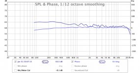
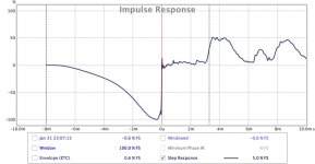
the last two days i am trying to do a crossover using it. Like i said i already have designed analog active crossovers before. So today i made a cross using LR48 IIR filers everywhere for my 3way design. Then i use FIR filter (for each driver) for driver equalizations and for phase correction. After many measurements and corrections i now have a cross which need further improvements but already sound better than my analog one. Look at the two photos and tell me your opinion. I have never seen step response like this on my analog cross before. Can someone "read" something from it? On the first picture is the frequency response (using windowing of course) and the phase response. on the second one is the step response. Of course when i invert the mid driver i get two deep notches at cross frequencies.
as i mentioned i already have the minisharc board. I designed a mainboard for the minisharc board. The mainboard has an ADC , optical and coaxial digital receiver, I2s switches, buffers-clock drivers , four stereo Dac's, cs3318 (8ch analog volume control) opamp line drivers and microcontroller which controls everything. (any many more is's like low noise regulators for every ic, isolators etc.)
the last two days i am trying to do a crossover using it. Like i said i already have designed analog active crossovers before. So today i made a cross using LR48 IIR filers everywhere for my 3way design. Then i use FIR filter (for each driver) for driver equalizations and for phase correction. After many measurements and corrections i now have a cross which need further improvements but already sound better than my analog one. Look at the two photos and tell me your opinion. I have never seen step response like this on my analog cross before. Can someone "read" something from it? On the first picture is the frequency response (using windowing of course) and the phase response. on the second one is the step response. Of course when i invert the mid driver i get two deep notches at cross frequencies.
Attachments
Last edited:
After measuring the bare speaker transfer function, one can easily determine the required FIR filter transfer function. This is B / A.
Oops, this is incorrect. I inadvertently chopped such paragraph while thinking about how to quickly expose the pitfalls and dangers of a transfer function inversion problem. I'm talking about an inversion here, because it is required to compute the inverse of B / A. Sorry about this.
The above paragraph should read instead:
After measuring the bare speaker transfer function (this is A / B), one can make an initial guess of the required FIR filter transfer function. This is (B / A) multiplied by the target (ideal) filtered speaker transfer function.
As you can see, I decided not to go into the details of the inversion problem.
For the ones that are taking the time reading me, and to keep a long story short, the computation of the required FIR filter transfer function leads to some usable solution, provided it doesn't generate high gains, doesn't generate brutal phase shifts, and most important, doesn't require the output to come before the input.
It is there that specifying some additional delay, and precisely controlling the distance that's separating the measurement mike from the measured speaker, takes importance.
It is also there that what's concerning a woofer, one must specify as target (ideal) filtered speaker transfer function, a highpass at say 50 Hz along with the crossover lowpass at 3400 Hz, for avoiding the target (ideal) filtered speaker transfer function asking for an infinite gain at DC, and for some intolerable high gain below 20 Hz or so.
It is also there that what's concerning a tweeter, one must specify as target (ideal) filtered speaker transfer function, a lowpass at say 15 kHz along with the crossover highpass at 3400 Hz, for avoiding the target (ideal) filtered speaker transfer function asking for some intolerable high gain above 20 kHz.
I can tell you that using such precautions, the initial guess of the required FIR filter transfer function is very good.
The vast majority of FIR filters generators consider the job to be done at this stage. They don't go past what I call here "the first guess". I'm talking about RePhase and the likes, asking you to manually import an impulse response, possibly averaged.
The system I'm advocating for, is better. As previously described, past what I call the "initial guess", that is based on several measurements that get averaged, the system I'm advocating for, is periodically comparing the realized transfer function, against the target (ideal) transfer function, which enables it to periodically send updated FIR filter coefficient lists. The Windows PC executing the FFT analysis and FIR filter management has enough computing power for applying advanced averaging in real-time, by time-domain IIR-lowpass filtering all frequency domain data before applying the inverse FFT that's delivering the FIR coefficient list. This brings a double win : averaging, and real-time monitoring. This way you can see in real-time what's happening when you change the measurement microphone distance and/or orientation.
As the ESI MAYA44USB+ features four analog line inputs, there is one left unused. One could add a second measurement mike preamp on the $ 50 board. The second measurement mike could be mounted on a robotic arm, enabling to simultaneously display the realized transfer function, both in-axis (fixed mike) and off-axis (movable mike). Just an idea.
The frequency curve looks ideal indeed, and your ears and the reverse medium experiment confirm it. I can understand this crossover to sound better than many others.On the first picture is the frequency response (using windowing of course) and the phase response. On the second one is the step response. Of course when i invert the mid driver i get two deep notches at cross frequencies.
Phase curves need to be taken with precaution.
Can you please repeat the reversed medium test, and tell if the phase curve then gets bumped. If this not the case, your FFT analyser is lying to you, meaning that the step response is not worth looking at.
As complementary tests, can you please repeat the "in phase medium" and "reverse phase medium" tests, with the FIR equalizing being disabled ? And look at the phase curve and step response curve ?
Here is how I see the step response that you provided. I guess that by "step", you don't mean a Dirac (short impulse). I can see there is a lot of low frequency energy, thus definitely not a Dirac. The step response looks excellent, strong low frequency buildup, excellent high frequency transient at time zero, and well controlled ringing at time zero (should zoom in time for better assessing if the awaited time-symmetry promised by a global linear phase shows there). Past time zero, the bass decay looks obliterated, replaced by a naughty series of square waves approaching 50% of the amplitude, each approx 2ms long. That's weird indeed.
What FFT analyzer are you using, in which modality ?
- genuine two channel analyzer (one hardware channel for the Reference signal, one hardware channel for the Measured signal, and the gain and phase computation being M/R instead of M only)
- simplified two channel analyzer (only one hardware channel for the measured signal, and a reference signal that's digitally assumed, and hence, requiring careful time alignment because of unknown delays in DACs, ADCs, USB audio and operating system)
- single channel analyzer that can't measure the phase, however dare to display a phase assumed to be "minimum" which is plain wrong in case of speakers featuring passive Linkwitz-Riley crossovers inside, whose global output is by definition, not minimum-phase.
In case we get completely lost, try getting your hands on a 2-way speaker having a passive Linkwitz-Riley crossover inside. It may serve as reference, for qualifying your FFT analyzer.
That's all I can say at the moment.
Hope this will have triggered some valuable new ideas.
Cheers,
Steph
Last edited:
hello Steph, thank you for your answer. I already have the reversed midrange fr. response. later i will make some mesurements and upload the response without FIR. All the measurements are made using REW and umik microphone- sweep 20 to 20k.
Which settings (in rephase) works best and i should use like hamming etc.. for the minisharc?
Which settings (in rephase) works best and i should use like hamming etc.. for the minisharc?
Attachments
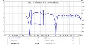
Last edited:
- Status
- Not open for further replies.
- Home
- Source & Line
- Digital Line Level
- My new minisharc dsp audio preamplifier/crossover project