Some of you may remember a while back I was experimenting with transformers as phase splitters. I eventually ordered a pair of PSA-2N phase splitters from Electra-Print. They are actually autoformers rather than transformers.
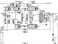
I decided to try them in a PP EL84 amp. Jack has a schematic for one on his site but I decided to roll my own. See attached schematic.

I finally got to the stage where I can test the amp. I'm "borrowing" a power supply from another amp since my new PTX isn't here yet. The B+ I'm getting from the borrowed PS is perfect for the new amp, I just had to drop in an additional RC filter to obtain the B2+ for the input stage. Attached is the PS schematic I'm using now. The new PS will be similar except it will use a 5AR4 and electrolytics rather than motor runs for the caps. (No room in the chassis for the big motor runs.)
Here is the PS I'm testing it with. The actual PS will be similar.

Here is the topside. Keep in mind the PTX and 5AR4 are yet to be mounted. The chokes will mount on the underside. The cage over the OPTs is a wire basket from Container Store (about $4 IIRC) held down with a couple of plastic wire routing tabs.
Front-

Back-

I put the inputs on the back. I like the front to look clean with only an On/Off switch.
Inside-

The autoformer phase splitters are mounted between the turret board and the back of the amp. They are immediately below the OPTs, probably not the best place but I can't hear any hum so I may not move them.
I decided to try them in a PP EL84 amp. Jack has a schematic for one on his site but I decided to roll my own. See attached schematic.
I finally got to the stage where I can test the amp. I'm "borrowing" a power supply from another amp since my new PTX isn't here yet. The B+ I'm getting from the borrowed PS is perfect for the new amp, I just had to drop in an additional RC filter to obtain the B2+ for the input stage. Attached is the PS schematic I'm using now. The new PS will be similar except it will use a 5AR4 and electrolytics rather than motor runs for the caps. (No room in the chassis for the big motor runs.)
Here is the PS I'm testing it with. The actual PS will be similar.
Here is the topside. Keep in mind the PTX and 5AR4 are yet to be mounted. The chokes will mount on the underside. The cage over the OPTs is a wire basket from Container Store (about $4 IIRC) held down with a couple of plastic wire routing tabs.
Front-
Back-
I put the inputs on the back. I like the front to look clean with only an On/Off switch.
Inside-
The autoformer phase splitters are mounted between the turret board and the back of the amp. They are immediately below the OPTs, probably not the best place but I can't hear any hum so I may not move them.
Nice design. I think transformers/chokes as phase splitters makes a lot more sense than more tubes. Seems much more elegant to me.
You might try replacing the resistor plate load with a simple CCS -- performance will likely go up and the need for large electrolytics and the extra filter stage to drop voltage will go down. I think there is plenty of space on the side for some motor runs.
-d
You might try replacing the resistor plate load with a simple CCS -- performance will likely go up and the need for large electrolytics and the extra filter stage to drop voltage will go down. I think there is plenty of space on the side for some motor runs.
-d
Thanks,
I think the autoformers are a nice solution, no extra tube sockets, lower demands on the PS, easy to implement. I'm tempted to try a pair in a PP KT88 amp.
I have some of the Forum CCS boards, I'll have to look into that. Would a current source (plate load) be better case than a current sink after the cathode?
I've also thought about removing the cathode bias on the EL84s and going with fixed bias. I'd have to do a voltage divider off the HT supply though since the PTX doesn't have a bias tap. Should be doable.
This is bad... thinking about mods and the amp isn't even completely finished yet!
Sherman said:I have some of the Forum CCS boards, I'll have to look into that. Would a current source (plate load) be better case than a current sink after the cathode?
You want it as a plate load where it presents a super high impedance to the tube. With the 6N1p, you can run it at about 11mA and bias it with a red led (instead of the resistor/cap pair) which will also offer a nice performance bump.
dsavitsk said:Nice design. I think transformers/chokes as phase splitters makes a lot more sense than more tubes. Seems much more elegant to me.
I agree. the circuit is pretty elegant. My only concern is the particular phase splitting autoformer chosen--- has only 10 henries of pri L on the driven half--- which will not provide much of a load impedance to the anode of the tube.
In defense of Jack at EP--- this unit (according to a spec sheet he used to have on line) was really designed to be driven by a cathode follower--- where the source impedance (i.e., the output impedance of the CF) is say a hundred or so ohms--- in which case 10 henries
(whose ind reactance at 20 hertz is approx 1250 ohms) would be perhaps a sufficiently high impedance---
but if the source impedance (the r sub p of your anode) is derived from the anode and it is several kilohms in magnitude--- that same 10 henries is not going to provide much of a load to the anode of the tube.
:::You might try replacing the resistor plate load with a simple CCS -- performance will likely go up and the need for large electrolytics and the extra filter stage to drop voltage will go down. I think there is plenty of space on the side for some motor runs.::::
it is a neat circuit--- and a builder could have several choices of how to load the anode---- with a resistor, a CCS, or a plate choke. But the achillles heel as drawn is the lack of L in the driven half of he autoformer.
This L will be in parallel with whatever is sitting on top of the anode---- so that 1250 ohms in parallel with a CCS is still going to be less than 1250 ohms effective impedance.
Of course as your frequency goes up--- so won't the inductive reactance of the autoformer's driven half.
but as is--- the limiting factor is going to bee the ten henries.
But--- I too like the circuit very much--- it conceptually very close to the SETH amp as shown on our forum at AA.
MSL
Probably worth a call to Jack. He is selling it as a plate load, and my experience is that model numbers don't mean a whole lot with him. He may have wound it differently than in the past, or just called it the wrong thing. Who knows. But, I'd give him a ring.
Well, you can still use a CCS and use the mu-follower output to present a lower impedance to the splitter choke. One of my old amp was pretty much build this way. I loved it.
Ciao
Gianluca
Ciao
Gianluca
Thanks for all the feedback.
I don't have any experience with the Electra-Print phase splitter autoformers except for this project. I breadboarded 1 channel before cutting metal and it seemed to work fine. The schematic for these phase splitters on the Electra-Print site isn't for a cathode follower so my assumption was they would work and so far they seem to.
I haven't really pushed it yet, nor have I connected it to decent speakers. All I can say at this point is that the 6N1P doesn't seem to be having a problem with the autoformers and it "sounds right".
With an 8 ohm dummy load connected I fed it a couple frequencies of sine wave and turned up the volume a little (about 6 watts output) and didn't see anything frightening on the scope. The 6N1P seemed happy, no glowing plate, no runaway oscillation.
I didn't do much else since 1- I didn't have time and 2- I want to build the PS before putting it through its paces so to speak.
And speaking of PS, with that 12" x 10" chassis I might be able to shoehorn in the planned 5AR4, a couple of 40uF motor runs and a single choke but it would be tight. My PTX will arrive soon so I can work on the final PS.
You should check the low frequency response.. The inductance in the choke and the capacitance of the coupling cap will make a resonance {f = 1/(2Pi x SQRT(L x C)}. This frequency should stay outside the audio band.
In this case, if L=10H and C=1uF, this resonance will be at ~50Hz.
Jan E Veiset
In this case, if L=10H and C=1uF, this resonance will be at ~50Hz.
Jan E Veiset
Hi,
I'm wondering has anyone try using the power toroidal transformer as the phase splitter autoformers in thiw sacd?
I'm wondering has anyone try using the power toroidal transformer as the phase splitter autoformers in thiw sacd?
You should check the low frequency response.. The inductance in the choke and the capacitance of the coupling cap will make a resonance {f = 1/(2Pi x SQRT(L x C)}. This frequency should stay outside the audio band.
In this case, if L=10H and C=1uF, this resonance will be at ~50Hz.
This is probably why the henrys aren't causing as much damage as expected. The circuit is working as a tuned tank to introduce a bass boost- quite clever if everything falls into place, horrible if it doesn't. I had this initially with my amp, I increased the parafeed cap from 1uf to 4uf and it went away.
Could the performance be improved by adding in some extra henrys in the earth center leg.
Hi,
I'm wondering has anyone try using the power toroidal transformer as the phase splitter autoformers in thiw sacd?
My current amp does exactly that. It works well, but certainly not as well as a good expensive interstage transformer. The problem is that the secondaries are wound over the top of the primary. This inevitably results in ultra high interwinding capacitance which kills high frequency response. There is a solution - push huge amounts of current through the transformer. I Have 40mA of drive current into mine, and I would probably only need about 15mA if I was using a proper interstage transformer. It works but its a bit wasteful.
Shoog
I built a PP EL34/KT88 using a CT choke too.
Initially, I have an CT choke/autoformer with 10H on each leg and it worked fine.
After reading this thread, I ask my winder friend to wind me another CT choke/autoformer with bigger core and higher inductance (around 120H each leg), it seems that this would improve my frequency response. When I installed this higher inductance ct choke phase inverter, the bass guitarist on all my music sources went home early and the drummer are just hitting the high hats! 😕
I somehow improve the response by biasing my driver (6n1p) hotter (am using parallel triode of the 6n1p, biased at 10ma combined).
I really don't know the math of the frequency response using autoformer/ct choke as phase inverter, but my findings contradict some of the posts on this thread.
I am going back to the 10H CT choke phase inverter to bring back the bass guitarist and complete the drummers drum set!
akexg,
are you sure that the phasing was correct? one quick check is to supply about 6volts ac from ct to one end, then you should get twice that from end to end if phasing was right....
are you sure that the phasing was correct? one quick check is to supply about 6volts ac from ct to one end, then you should get twice that from end to end if phasing was right....
Tony said:akexg,
are you sure that the phasing was correct? one quick check is to supply about 6volts ac from ct to one end, then you should get twice that from end to end if phasing was right....
Am sure the phasing is right.
I noticed this even when I breadboarded the circuit.
I have been trying to figure out what is going on, but so far I can't explain what is happening.
I will be using a pair of Lundahl interstage tonight and see what happens, so instead of a CT choke or autoformer for phase inversion, I will be using an interstage (SE to PP).
Last night I even tried a very small Talema toroidal's primary as autoformer phase inverter and it has much better bass than the 120H CT choke/autoformer that my friend wound for me. (This Talema mains toroidal transformer has around 5H on the primary). Unfortunately when I asked my friend if he did a simple interleave on the winding, he told me he used one section of the dual section bobbin for one leg of the autoformer and the other section for the other leg.
I wish somebody can explain what is going one. Thanks. 🙁
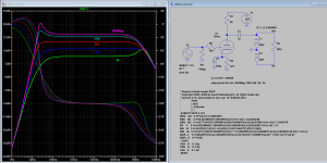
In the original Electra-Print PSA schematic there's a 100k grid to grid resistor that's parallel to the autoformer. Sounds "better" subjectively in place but some builders like Sherman leave it out. I initially used a pot to adjust for distortion as suggested by Jack.
Can someone explain the purpose of this resistor and how it's value is calculated? It doesn't appear to be a grid leak nor a stopper (or is it?). I've looked through the usual modern books and a few engineering text like Terman. Can't find the answer. Thanks.
Can someone explain the purpose of this resistor and how it's value is calculated? It doesn't appear to be a grid leak nor a stopper (or is it?). I've looked through the usual modern books and a few engineering text like Terman. Can't find the answer. Thanks.
The purpose of shunt resistor across the transformer is 1) as termination to damp the ringing 2) to control the corner frequency of top and bottom end. Attached sim (as example) shows the best value would be 25k or so, depends of amount inductance hence the corresponding value of resistance to attain the result.
Attachments
I was just wondering about this resistance. There is little time, I now have a beginning of answer. and what is it when this resitance has in addition a capacitor in series?
I ask the question because I have an amp that has this type of mounting (resistance + capacitor) on the secondary of the opt
I ask the question because I have an amp that has this type of mounting (resistance + capacitor) on the secondary of the opt
Attachments
This RC network is called a Zobel, and applies damping only to the higher frequencies, minimizing loading on the amplifier.
All good fortune,
Chris
All good fortune,
Chris
The Sound Grail Tube amplifier Schematic
Yes, it's possible to use more than 1 Zobel network, so as to attain sharper impedance cut off at upper end.
Yes, it's possible to use more than 1 Zobel network, so as to attain sharper impedance cut off at upper end.
Attachments

- Status
- Not open for further replies.
- Home
- Amplifiers
- Tubes / Valves
- My New EL84 PP