I would hesitate to put two ground points at either end of the ground trace, because the very high charging pulses may cause hum between the two ground points.
For the 1R resistors, I would avoid wirewound as that may make diode glitches ring badly.
For the 1R resistors, I would avoid wirewound as that may make diode glitches ring badly.
That looks OK.
The only advice I can give is to just think as you wire it all up. Did I post a link some way back as to where it all went wrong in connecting two PCB's of the "blameless class B" to a single PSU ? It was here anyway... make sure you understand the problems 🙂
http://www.diyaudio.com/forums/solid-state/101321-3-stage-lin-topology-nfb-tappings.html
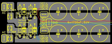
Keantoken , OK this is easy but what about moving the center tap GND to the middle of the trace? Will this be good or will need again second connection and will this second wire not create a GND loop with the first and the trace and make things worst? Also my resistors are carbon film.
Mooly , you posted this in the past and I learned my lesson 🙂 - will take speaker GND directly from the PSU - PCB is made like this no way to take speaker GND from it.
Mooly , you posted this in the past and I learned my lesson 🙂 - will take speaker GND directly from the PSU - PCB is made like this no way to take speaker GND from it.
If the left ground connector only connects to the transformer center tap then I don't see it being a problem. I would put the amp ground connectors next to the CT connector at the left side of the ground trace, and and run the PSU ground wires back across the ground trace to be braided (or heatshrinked) with the other PSU wires for magnetic cancellation. Same for the transformer wires, as the rectified pulses and diode glitches may ring with the transformer. This way physically wide current loops are avoided, so less radiation.
Another thought is that braiding or heatshrinking supply wires decreases inductance between the reservoir caps and the on-board caps and decoupling. This inductance otherwise may ring with the onboard caps. At high frequencies no amp has good PSRR, so ringing rails can cause an amp to oscillate.
Another thought is that braiding or heatshrinking supply wires decreases inductance between the reservoir caps and the on-board caps and decoupling. This inductance otherwise may ring with the onboard caps. At high frequencies no amp has good PSRR, so ringing rails can cause an amp to oscillate.
OK let see did I understand you correct - to make GND points as close as possible with the center tap , move the +/-V connections and when ready to wire the all thing to braid all +/-V and GND wires and put them between the caps like shown on the picture. Of course on the picture wires are not can't draw them braided 🙂
This is the idea isn't it?
P.S. Isn't a good idea to have 100nF decoupling caps just before the +/-V connectors ?
This is the idea isn't it?
P.S. Isn't a good idea to have 100nF decoupling caps just before the +/-V connectors ?
Attachments
Last edited:
You have local decoupling on the amp PCB which is where it really counts.
OK true...not a good idea...
Astankov, you have the basic idea, but I was wanting to leave the +-V supply connectors at the end of the board, so they come after the supply caps, as this will improve filtering. The ground wire is brought back across the ground trace and then at the end of the board braided with the supply wires.
Astankov, you have the basic idea, but I was wanting to leave the +-V supply connectors at the end of the board, so they come after the supply caps, as this will improve filtering. The ground wire is brought back across the ground trace and then at the end of the board braided with the supply wires.
OK now should be right.
Green wire will be the GND and at the end of the board will be braided with +/-V wires.
Attachments
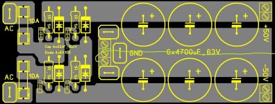
Yes, that's what I was thinking. Good luck.
OK at least I understand you correct 🙂
Will etch the board ASAP. Expect pictures.
Regards!
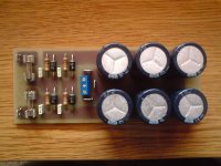
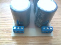
PSU Board Ready...
Here is the PSU board - tested and ready to be installed.
See how it looks on the pictures.
Next will be turn on delay and DC protection for the speakers. Can you recommend me a schematic and PCB for this?
Regards!
Here is the PSU board - tested and ready to be installed.
See how it looks on the pictures.
Next will be turn on delay and DC protection for the speakers. Can you recommend me a schematic and PCB for this?
Regards!
Attachments
Nice. Unfortunately I haven't messed with speaker protection stuff yet.
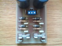
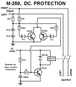
I read about the schematic on the picture in one site - they said it is working well what you think?
If is OK will make a PCB. It needs 12VDC so will it be a good idea to put on the board a voltage stabilizer with zener and transistor and use the +50V to supply the board?
Attachments
Offest protection is controversial subject. The biggest problem is getting relays to survive when they have to work for real. Contacts can weld together.
I would really recomend you read all of this for interest. It's about using FET's in place of relays... and they work brilliantly. PMA has a neat design toward the end. Read it all.
http://www.diyaudio.com/forums/solid-state/191449-output-relays.html
I would really recomend you read all of this for interest. It's about using FET's in place of relays... and they work brilliantly. PMA has a neat design toward the end. Read it all.
http://www.diyaudio.com/forums/solid-state/191449-output-relays.html
Kean,
that circuit in post154, will not work well.
The base current of the TIP is too low. The switching transistor will run hot. You need lots of base current to saturate the switching transistor.
The 12V used for the delayed pull in needs to come up reliably. If that 12V is variable during start up or during operation then the relay pull in time can vary enormously, even becoming infinite time delay.
I don't like the two Zeners in the DC detection. Too high a voltage needed to trip the speaker switch.
Mooly , the idea for an SS relay with MOSFET's is great but I think we make things overcomplicated here - most of my idea is to have turn on delay and protection to be like an bonus to the schematic to have it just in case - this will not be an pro amp but one for home listening and maybe for a not very loud parties time to time.
Andrew , the TIP121 is darlington and the base current is too low?
In original version schematic does not have the zeners it has two diodes instead but there are reports for lots of false turn offs so they put the zeners. I don't like them too can I substitute them with two red LED's? Also as I said before the 12V will be supplied trough stabilizer with transistor and zener and this will make them reliable but will the transistor not become very hot if I use the +50V for supply?
Hi, may I suggest as what I am using now.
No need for separate dc supply. Just tap AC from transformer secondary from say 25Vac to 40Vac.
I have delay turn on and DC protect at +/-1.5 to 2Vdc.
There is fixed voltage of 24V for operation on board.
Cheers.
No need for separate dc supply. Just tap AC from transformer secondary from say 25Vac to 40Vac.
I have delay turn on and DC protect at +/-1.5 to 2Vdc.
There is fixed voltage of 24V for operation on board.
Cheers.
Attachments
Hi, may I suggest as what I am using now.
No need for separate dc supply. Just tap AC from transformer secondary from say 25Vac to 40Vac.
I have delay turn on and DC protect at +/-1.5 to 2Vdc.
There is fixed voltage of 24V for operation on board.
Cheers.
RSK , can you share the schematic?
This type of relay is not available to me and will have to make a different PCB so I will need the schematic.
Regards!
- Status
- Not open for further replies.
- Home
- Amplifiers
- Solid State
- My new design or updated old one