That's good for a first attempt I'd say 🙂
My first ones were all hand drawn with etch resist pens... no pc's !
So what now ? Build it up... version V1.00 😉
My first ones were all hand drawn with etch resist pens... no pc's !
So what now ? Build it up... version V1.00 😉
Of course that will build it 🙂
I maybe heated up the toner too much and too long so it is not perfect.
Next time will heat it not that long and I hope will be much better.
I drilled the board and tomorrow will heat up my soldering iron.
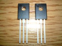
I also ordered some parts and they arrived today only one thing - arrived not MJE340/350 but KSE340/350 they seems to be Fairchild analogues in insulated packages I think is not a problem but asking costs no money🙂
So tomorrow will build it. Will post pictures.
Regards!
I maybe heated up the toner too much and too long so it is not perfect.
Next time will heat it not that long and I hope will be much better.
I drilled the board and tomorrow will heat up my soldering iron.
I also ordered some parts and they arrived today only one thing - arrived not MJE340/350 but KSE340/350 they seems to be Fairchild analogues in insulated packages I think is not a problem but asking costs no money🙂
So tomorrow will build it. Will post pictures.
Regards!
Last edited:
The KSE's are a recognised number, never used them myself but should be fine.
Good luck with the build... power it all up carefully... bulb tester maybe 🙂
Good luck with the build... power it all up carefully... bulb tester maybe 🙂
For test will use lower voltage +/-25V and the bulb tester is always with me.
Also will use irf640 just to make sure all is OK after that will go with big boys IRFP260N.
See how KSE's looks. They are in insulated packages. Never seen this package.
Also will use irf640 just to make sure all is OK after that will go with big boys IRFP260N.
See how KSE's looks. They are in insulated packages. Never seen this package.
Attachments

I've never used any insulated T0126 packages. Have come across plenty of all plastic T0-220 style such as BUT11AF's and all plastic BUxxx devices.
With a bulb tester and the FET's on a heatsink I don't think you would damage them even if there were a problem somewhere.
With a bulb tester and the FET's on a heatsink I don't think you would damage them even if there were a problem somewhere.
Astankov, try my Kmultipliers. These versions are for high-current. I found they had more effect on my BJT amps rather than FET, but in all cases they seemed to improve the bass and accuracy. Keep the layout compact. The output impedance rivals electrolytics, so it will be like giving your amps 100mF capacitors at normal listening levels (the Kmultipliers don't actually store energy so they are most useful for filtering).
- keantoken
- keantoken
Attachments
Well maybe will try them 🙂
Transistors can be substituted I think because here is full of fakes 😡
Is there any requirement except Vce when choosing devices in this case?
Transistors can be substituted I think because here is full of fakes 😡
Is there any requirement except Vce when choosing devices in this case?
Q3 and Q6 could be replaced with BD139/140 I think, and maybe the MJE243/253. The 2SC5200/A1943 need to be replaced with fast toshibas if possible. The BC560C/550C should be real, they are critical. If not, high-gain transistors should be used, and while output impedance will still be low filtering may suffer.
R15 and R16 need to be chosen for a good bias current for the green LEDs, this can probably be between 5mA-20mA, if you want to lower the power rating of these resistors.
R15 and R16 need to be chosen for a good bias current for the green LEDs, this can probably be between 5mA-20mA, if you want to lower the power rating of these resistors.
Oops, forgot to say, I used those Kmultipliers for 24V, but for higher voltage I would add a 470R resistor in series with the Red LED. This is because the inrush current for C2 and C4 will destroy it unless you have a soft turn-on circuit.
- keantoken
- keantoken
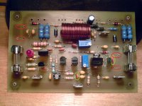
Ver1.0 Finished!
Well here it is 🙂
Worked well but there were some problems also.
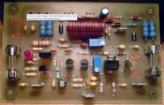
When checked the layout didn't noticed that 2 caps are missing - C3 100pF from input to GND and VAS compensation C22 - 33pF. On picture marked with green. How can I miss that. I'm very angry to myself 😡 Anyway managed to solder them somehow.
Other stupid think I did is to post a wrong schematic -the input was drawn wrong. Attaching correct one. Yet another mistake on the PCB and again because of me 😡 I'm such an idiot...
So powered up set the bias and offset and listened. Sound was like I expected.
The only thing is that I have some light brum - measured the AC at the output was 0.005VAC. That is very strange when tested the schematic and all was on a veroboard and everything was connected with long wires there was no problem. When tested everything was the same - same supply , again connected PCB with wires to drivers and outputs. What can be the problem , can be because I don't put the 100uF between +/-V and GND (marked red on the picture) since forgot to order them or because connected transistors with wires or maybe because using 10R between AGND and PSU GND 😕
So that was VER1.0
If Alex is reading I will be grateful to fix the mess that I made and have the correct board now. I need the TO126 version but if you want can make the TO220 version too.
Thanks and sorry for being such idiot and having my eyes on the butt...
Well here it is 🙂
Worked well but there were some problems also.
When checked the layout didn't noticed that 2 caps are missing - C3 100pF from input to GND and VAS compensation C22 - 33pF. On picture marked with green. How can I miss that. I'm very angry to myself 😡 Anyway managed to solder them somehow.
Other stupid think I did is to post a wrong schematic -the input was drawn wrong. Attaching correct one. Yet another mistake on the PCB and again because of me 😡 I'm such an idiot...
So powered up set the bias and offset and listened. Sound was like I expected.
The only thing is that I have some light brum - measured the AC at the output was 0.005VAC. That is very strange when tested the schematic and all was on a veroboard and everything was connected with long wires there was no problem. When tested everything was the same - same supply , again connected PCB with wires to drivers and outputs. What can be the problem , can be because I don't put the 100uF between +/-V and GND (marked red on the picture) since forgot to order them or because connected transistors with wires or maybe because using 10R between AGND and PSU GND 😕
So that was VER1.0
If Alex is reading I will be grateful to fix the mess that I made and have the correct board now. I need the TO126 version but if you want can make the TO220 version too.
Thanks and sorry for being such idiot and having my eyes on the butt...
Attachments
Well I'd say that was brilliant for a first attempt.
No matter how many times you stare at PCB's and circuits it can be easy to overlook something... I tend to put them on one side and then come back to them later and check and check again. It happens 🙂
You have hum (brum) ?
Is this with one amp or two (stereo pair) wired up ?
Have you scoped the output to make sure it isn't oscillating ? Any hum with the input shorted on the PCB ?
You need decoupling on the PCB.
And the 33 Ω to the gates MUST be right on the FET's if you are using wires for guaranteed stability.
That leaves where to put the zeners... do you really need them in practice ?
That leaves where to put the zeners... do you really need them in practice ?
I made only one PCB to make sure it OK and found problems so when get corrected will have a pair. Yes hum is present when input is shorted and no scope to check but seems to be a 50 Hz hum. Also offset is dead stable so I don't think it is oscillating. Yes used wires between transistors and the board just to confirm that PCB is working now can test without them. When testing on veroboard 33R were on board and again used wires and no hum also now I have more decoupling caps than in the test and have hum 😕
Zeners are to protect the gate aren't they. I was strongly suggested to put them earlier in the thread but can they be the reason for the hum?
Now waiting for correction and will have VER2.0 🙂
Zeners are to protect the gate aren't they. I was strongly suggested to put them earlier in the thread but can they be the reason for the hum?
Now waiting for correction and will have VER2.0 🙂
Hum... the frequency tells us a lot. If it is 50 hz that will be a pure deep tone (sine wave). If there are harmonics present it's more like a harsh "buzz" and at twice 50 hz (100) as it is then probably caused by the 100 hz ripple from the PSU entering the amp.
Does the hum increase if you alter the bias. More current drawn increases ripple on the rails so maybe worth doing that just to get an idea. Obviously watch the current but just taking it to half an amp and back down again over a couple of seconds should be fine. Watch for any sudden increase in current as that can be a sign of instability.
Yes, the zeners are for protection to limit Vgs and thus current... although I think in practice other things would have gone up as well if they forced into conducting. For normal domestic use and if you don't go shorting the outputs then I don't think they will ever come into play. If you connect the FET's direcet to the PCB then leave them be. I was just thinking of the 33 Ω being at the "wrong" end of the wire to the FET's that's all.
They won't cause hum 🙂
R36 will degrade cascode quality, why is such a large value necessary? Needing such a large resistor here for anything other than voltage drop would seem to indicate a problem.
The 2N5551/5401 are high-voltage transistors and will not perform well at low voltages. Try switching them with BC550 or 2N5089/5210 or MPSA18. This is most important for the current mirror at low Vce. This also applies to my Kmultipliers, which is how I discovered this.
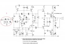
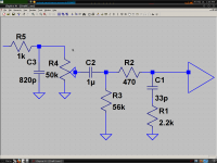
These last thoughts might be relegated to personal opinion, as you are doing it the conventional way, but I will speak. Your 100pF input filter makes a mockery of your 56k input impedance. Your volume pot's output impedance will combine with this cap to form a LP filter that changes with volume. I advize to change this to 33pF with a 2.2k resistor in series, and change the cap later on to be as small as possible without negatively affecting amp stability (hopefully 10p or smaller, and it may help to use 2N5210 or MPSA18 in the LTP). Your main LP filter should be before the volume pot, not after. This will avoid causing an unpredictable LP corner. See the attached schematic.
- keantoken
The 2N5551/5401 are high-voltage transistors and will not perform well at low voltages. Try switching them with BC550 or 2N5089/5210 or MPSA18. This is most important for the current mirror at low Vce. This also applies to my Kmultipliers, which is how I discovered this.
These last thoughts might be relegated to personal opinion, as you are doing it the conventional way, but I will speak. Your 100pF input filter makes a mockery of your 56k input impedance. Your volume pot's output impedance will combine with this cap to form a LP filter that changes with volume. I advize to change this to 33pF with a 2.2k resistor in series, and change the cap later on to be as small as possible without negatively affecting amp stability (hopefully 10p or smaller, and it may help to use 2N5210 or MPSA18 in the LTP). Your main LP filter should be before the volume pot, not after. This will avoid causing an unpredictable LP corner. See the attached schematic.
- keantoken
Attachments
Last edited:
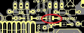
..... I have found one error , it seems D2 it's reversed in your picture .
I think bias cant be correct this way . 😉
It appears so... that's well spotted Alex 🙂
I'll look in again tomorrow 🙂
See how it's all going.
------------------------------------------------------------------------------------------------------------------
Some good suggestions from Keantoken, maybe some things there you can try out on later versions/simulation.
See how it's all going.
------------------------------------------------------------------------------------------------------------------
Some good suggestions from Keantoken, maybe some things there you can try out on later versions/simulation.
Alex is the man! I really is reversed...yet another mistake god damn it.
This probably is the reason for the hum. Bias can be correct because all diodes are paralleled with 47R resistor so bias is correct just the diodes are not connected in the schematic. Will fix that but PCB needs a fix too and I hope Alex will do it.
Regards!
This probably is the reason for the hum. Bias can be correct because all diodes are paralleled with 47R resistor so bias is correct just the diodes are not connected in the schematic. Will fix that but PCB needs a fix too and I hope Alex will do it.
Regards!
- Status
- Not open for further replies.
- Home
- Amplifiers
- Solid State
- My new design or updated old one