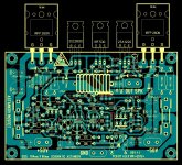
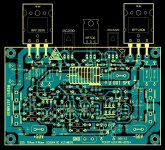
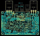
PCB all rev 1.1 and rev1.2
..... PCB rev 1.1 are layout for TO220 drivers , and rev1.2 for TO126 drivers 🙂
Regards Alex.
..... PCB rev 1.1 are layout for TO220 drivers , and rev1.2 for TO126 drivers 🙂
Regards Alex.
Attachments
Thank you Alex...just one last fix in version 1.1 you forgot to correct the 82R to output issue...in version 1.2 is correct.
When you correct it I'm gonna edit the first post of the thread to become schematic and PCB's more visible and easy available to anyone who will read the thread.
Cheers!
When you correct it I'm gonna edit the first post of the thread to become schematic and PCB's more visible and easy available to anyone who will read the thread.
Cheers!
Last edited:
Well Mooly this is the reality - my country is flooded with fake devices of any type.
That's why I told you that can have only a limited amount of transistors. I supply them from
a person who directly imports them from the factories a person that will never sell a fake because is an audiophile and knows really well that selling fakes will destroy it's reputation.
He is not a business man and it is not selling transistors for profit - it is a hobby pearson just like me. My other supplier is a commercial and sells a wide range of
devices but intentionally avoiding to sell any devices that can be made fake like 2SC5200/2SA1943 or MJL1302/MJL3281 and many others - it sells only original devices but with limited use in audio - IRFP250N , IRFP260N , IRFP460. It also sells BD139/140 and MJE340/350 and I shopped many times from there and I'm sure that there is no fakes. It is the only reliable semiconductor retailer in my country.
Now you know why I build this amplifier because I'm sure that when buy some of it's parts will be original and in my previous post I pointed the devices
that I can have and they will be originals. Otherwise I can have any device in
the world but no guarantee that will be original.
A question - in my VAS there are three transistors connected in series - is this means that they will share each other the high voltage and I can use BD139/140 for CCS , cascode and VAS devices. Simulation confirms that but in reality can be different that's why I ask.
I played a bit with DipTrace and it is really difficult but I don't give up soon will have the PCB redrawn.
Best Regards!
As simulation will show you only have around 6 volt Vce accross T6, even a to92 transistor can be used here with a vas current around 10ma. The idea of using a cascode is for the purpose of reducing miller effect and increasing loop gain to reduce especially higher frequency distortion amongst others. To gain any benefits from using a cascode one has to chose the right parts for the job or otherwise the cascode makes no meaningful contribution and can actually make things worse if attention is not paid to other areas in the design. That would be like buying high speed rated tyres for your car but your car wont go any faster with them if you dont upgrade the engine for more power.
In contrary to what Mooly has said that the differences are small this is not the case in reality. Double the Cob of the vas transistor equates to double the high frequency distortion, its as simple as that. So say instead of getting 0.008 distortion you will get 0.016, thats not small difference at all. It will show in simulation as relatively small diffrence because of inaccuracies with models but if youre interested I can mail you some lab reports that demonstrate it. The reports were done by respected designer and also member here Samuel Groner, it partly also explains the mechanisims at work. Also have a look at designs from other designers, a good start and in particular with the setup you have here the Azur 640 amp. There the optimum transitor choices were made, to92 darlington vas transitor cascoded.
For the porpose of the cascode transistor high early voltage is the most prominent factor to consider followed again by its cob. In this position either the toshiba or 2sc2690 will be fine. A good indicator of early voltage is its Vceo, the higher the better early voltage. This goes for the current source transistor as well and here its even more important as early voltage influences PSRR and reduces assymetric drive to the driver transistors.
OK then what about using BF420/422 for VAS it has only 1.6pF output capacitance?
Power dissipation rating is marginal. They would run very hot and exceed their power rating under drive as the voltage swing across them varies.
You're still worrying 🙂
No worries Mooly just informative question🙂
Homemodder any design can be made better there is no best design. I think this one is good enough for middle class amp. Yes a car won't go faster with new tires but will handles better and some time handling is more important than speed. I think that cascode will always be better than a single transistor for VAS.
So my final device selection is MJE340/350 for CCS and cascode , BD139 for VAS
and TO220 drivers C4793/A1837 and that's it. If you don't like it use different types in your builds😎
Best Regards!
Moving on to when it's all complete 🙂
Have you thought about how you will wire the two PCB's up into a stereo amp ? Grounding and speaker returns. If you are using a common PSU have a look through all of this,
http://www.diyaudio.com/forums/solid-state/101321-3-stage-lin-topology-nfb-tappings.html
Have you thought about how you will wire the two PCB's up into a stereo amp ? Grounding and speaker returns. If you are using a common PSU have a look through all of this,
http://www.diyaudio.com/forums/solid-state/101321-3-stage-lin-topology-nfb-tappings.html
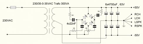
I read the thread and you suggesting to make my PSU like on the picture or I'm
wrong?😕
I've never used super fast or shottky diodes is it worth it or just to use standard ones like 6A10S?😉
About NFB it is already made on the PCB I don't wan't to change it it is really
beautiful.
wrong?😕
I've never used super fast or shottky diodes is it worth it or just to use standard ones like 6A10S?😉
About NFB it is already made on the PCB I don't wan't to change it it is really
beautiful.
Attachments
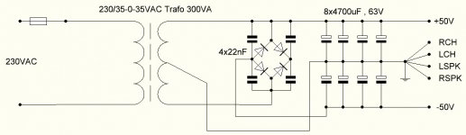
I would just use a standard bridge rectifier. That much capacitance will generate a large switch on surge through the diodes so something like these would be my choice,
Your Search Results | CPC | Results
I have always recommended adding caps across the diodes as shown although I have revised my thinking a little lately. I would perhaps now add a 1 ohm 1 watt carbon resistor (must be non inductive) in series with each. It has been mentioned that the cap and any inductance (tranny, wireing etc) can form a resonant peak so the resistor avoids that and still gives effective hf supression. I'm not a huge fan of oversized reservoir caps tbh. I would think 10,000uF per rail plenty. There are downsides to having to much as well as to little.
The other thread was really to highlight the problem of what happens when two amplifiers are connected to a common PSU and how the speaker return current in particular can influence the other channel. So have the speaker return back to the PSU star point and not connected to the ground terminal on the amp PCB.
No worries Mooly just informative question🙂
Homemodder any design can be made better there is no best design. I think this one is good enough for middle class amp. Yes a car won't go faster with new tires but will handles better and some time handling is more important than speed. I think that cascode will always be better than a single transistor for VAS.
So my final device selection is MJE340/350 for CCS and cascode , BD139 for VAS
and TO220 drivers C4793/A1837 and that's it. If you don't like it use different types in your builds😎
Best Regards!
Excellent choices for what you have at hand if you have original parts, it is as I was suggesting. As datasheets for bd139 are not detailed have a look at bc639, the bd139 is the same transistor die but put in to126 package to increase its dissapation. You will notice that it is in fact a fairly good vas transitor.
Mooly I really hate these bridge rectifiers😡 they make me big headache in several situations 😡 so will not use them will go for the standard discrete diodes - never had problems with them. About the capacitors across the diodes I didn't understand you very well - to connect 1R resistor where - in series with the diode or with the capacitor and capacitor stays or to remove it? A drawing will make my life easier 🙂
Homemodder at least a good words from you 🙂
About BD139 and BC639 well I didn't noticed that they are the same device in a different package. Thanks for advising me!
Homemodder at least a good words from you 🙂
About BD139 and BC639 well I didn't noticed that they are the same device in a different package. Thanks for advising me!
Last edited:
Resistor goes in series with each 22nf cap in your drawing. So that's 4 resistors, one for each 22nf cap.
The problem of RF interference is real and something I encountered myself on an Hitachi radio. It buzzed loudly on FM. A 0.1 uf across the transformer secondary killed the noise completely. Again, I would now add a resistor in series with the cap.
The problem of RF interference is real and something I encountered myself on an Hitachi radio. It buzzed loudly on FM. A 0.1 uf across the transformer secondary killed the noise completely. Again, I would now add a resistor in series with the cap.
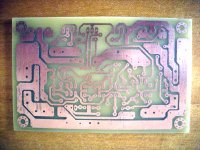
Guys I'm etching the PCB right now REV1.2 TO126 drivers turn out that my supplier have problem supplying me with C4793/A1837 so MJE's will be used for the test of the PCB.
Question - with what to remove the toner from PCB when etching is done - nail polish remover or anything else like petrol or something. This thing is very resilient to chemicals 😡 I made an bad transfer of the toner on one board and tried to remove it with alcohol but no success so need help please with that.
Will post pictures of the board when compelete.
Regards!
Never used the toner method. I guess cellulose thinners would remove it... seems to remove pretty much everything.
Make sure the PCB is totally clean after thinners or whatever you end up using.
Make sure the PCB is totally clean after thinners or whatever you end up using.
- Status
- Not open for further replies.
- Home
- Amplifiers
- Solid State
- My new design or updated old one