OK BD139 is better but schematic will be used with +/-50V is this not too much for it?
Other thing is that not the all parts in the world are available to me so I'm choosing something that I can have. This schematic is created for purely hobby purposes and I'm a hobby person not a design engineer so don't have the needed equipment to provide real measurements. I build it and listened - sounds very good to me and this is more important than anything I think. When schematic was posted I asked for comments - there were none and because of that decided that is good and nothing is wrong.
This is not the best amp in the world and if you don't like it don't build it , if you like it build it you won't regret. I will be happy someone to build it and post some real world measurements and then to comment what is wrong and how to fix it or make it better.
Best Regards!
Last edited:
Yes that's looking good.
In Diptrace I can right click a pad and change properties (size, shape etc).
I always "design" onto PCB directly. I never use the schematic option for PCB design.
Here's some I made earlier 🙂
http://www.diyaudio.com/forums/head...-ended-class-headphone-amp-2.html#post2095817
http://www.diyaudio.com/forums/soli...-built-listened-d-selfs-precision-preamp.html
Have a play with these Diptrace files,
Attachments
Because the vas transistor is cascoded the voltage accross it is much reduced, you could even use much higher voltage supplies. Nothing wrong with the design, it will just optimize it.
Thanks Mooly for the files will give it a try.
As I said found the solution for the pads in my software. DipTrace is complicated
so much but will give it a try anyway.
Homemodder , I can have BD139/140 , 2SC4793/2SA1837 , 2SC2690/2SA1220 and MJE340/350.
What you will recommend me for VAS transistor , cascode transistor and drivers
to make the schematic better?
My feeling on this is that the realities of different transistors will really only show under detailed lab testing. And then it's the nnnth degree of not very much 😉
I would be concerned with making sure that what ever you can get are genuine devices. Even long before the days of widespread internet use and before I ever heard of devices being fake and so on I remember some MJE340/350's that when rubbed revealed a BDxxx number underneath. They were from a major established parts supplier... one of todays biggest and most respected.
You're doing a great job with it all 🙂
Well Mooly this is the reality - my country is flooded with fake devices of any type.
That's why I told you that can have only a limited amount of transistors. I supply them from
a person who directly imports them from the factories a person that will never sell a fake because is an audiophile and knows really well that selling fakes will destroy it's reputation.
He is not a business man and it is not selling transistors for profit - it is a hobby pearson just like me. My other supplier is a commercial and sells a wide range of
devices but intentionally avoiding to sell any devices that can be made fake like 2SC5200/2SA1943 or MJL1302/MJL3281 and many others - it sells only original devices but with limited use in audio - IRFP250N , IRFP260N , IRFP460. It also sells BD139/140 and MJE340/350 and I shopped many times from there and I'm sure that there is no fakes. It is the only reliable semiconductor retailer in my country.
Now you know why I build this amplifier because I'm sure that when buy some of it's parts will be original and in my previous post I pointed the devices
that I can have and they will be originals. Otherwise I can have any device in
the world but no guarantee that will be original.
A question - in my VAS there are three transistors connected in series - is this means that they will share each other the high voltage and I can use BD139/140 for CCS , cascode and VAS devices. Simulation confirms that but in reality can be different that's why I ask.
I played a bit with DipTrace and it is really difficult but I don't give up soon will have the PCB redrawn.
Best Regards!
Last edited:
Alex it is so beautiful...no words to express my feelings right now... You are the only person that do something for me just like that for help and fun.
There is no much persons like you left in the world....big THANKYOU man!
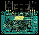
The only thing I noticed is that drivers are in TO126 packages and have different
pinout ECB and not BCE like the TO220 that you used but really no problem will use TO220 drivers in this board that is a piece of art.
Well you deserve a beer and Romania is not that far way from me one day you may have it🙂
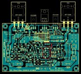
Edit... noticed that the emitter of the 2SC2690 needs to be connected trough 82R to the output and then the the diodes in series to the 2SA1220 driver emitter. The link between the 82R and output is missing.
Thanks very much again!
Best Regards!
You are the only person that do something for me just like that for help and fun.There is no much persons like you left in the world....big THANKYOU man!
The only thing I noticed is that drivers are in TO126 packages and have different
pinout ECB and not BCE like the TO220 that you used but really no problem will use TO220 drivers in this board that is a piece of art.
Well you deserve a beer and Romania is not that far way from me one day you may have it🙂
Edit... noticed that the emitter of the 2SC2690 needs to be connected trough 82R to the output and then the the diodes in series to the 2SA1220 driver emitter. The link between the 82R and output is missing.
Thanks very much again!
Best Regards!
Attachments

Last edited:
..... 😱 ok , corrected now , also I forget 100 pF capacitor B-C , 47 ohm resistor and 100nF capacitor around 3X1n4007 diodes .I have changed TO220 drivers to TO 126 as well . Can't be perfect at first layout as usual ....😉
Best regards Alex.🙂
Best regards Alex.🙂
Attachments

No problem Alex no one can be super perfect from first time.
Will observe it in detail and will post if I see some problem.
Thanks very much again!
Will observe it in detail and will post if I see some problem.
Thanks very much again!
A question - in my VAS there are three transistors connected in series - is this means that they will share each other the high voltage and I can use BD139/140 for CCS , cascode and VAS devices. Simulation confirms that but in reality can be different that's why I ask.
You have to think about the voltages under dynamic conditions as well as steady state. Imagine feeding a triangular wave as an input and you are driving the amp to the point of clipping. And lets say it is running on -/+50 volts.
That means that T15 collector can see anything from nearly as high as the positive rail and down to very near the negative rail. T16 sees a similar situation. So you need a Vce rating of at least 100 volts and for safety (to prevent secondary breakdown) a margin of say 20%. So if you were running 100 volt supply then 120 volt transistors for T15 and 16 would be reasonable. So BD139/140 aren't really high enough rated.
You have to look at all the voltages when the output is driven hard each way.
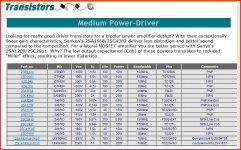
The Toshiba 2SC4793/2SA1837 you mentioned seem as good as any. T6 doesn't see that same voltage swing, even so I think I would go for a 2SC4793 here too as you know they are genuine.
Alex does great PCB's 🙂 he did one for my Lateral FET amp too.
Thanks Mooly for the explanation 2sc2690/2sa1220 are just 120VCE and they are suitable I think or not? Can use MJE340/350 if don't have choice.
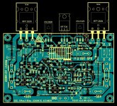
Alex we have a problem......
The resistors in the emitters of the current mirror and the middle pin of the offset trimmer need to be connected to -V and they are not....
Alex we have a problem......
The resistors in the emitters of the current mirror and the middle pin of the offset trimmer need to be connected to -V and they are not....
Attachments
MJE's will work fine if that is all you can get. The "A" version of 2sc2690/2sa1220 are 180 volts. 120 volt rating is perfectly OK though on 100 volt rails.
It's looking good 🙂
It's looking good 🙂
Now is OK 🙂
Alex can I be a bit greedy and tiresome to ask you for a variant with TO220 drivers.
Yes I know that I told you to change them...😱😱😱 but just wasn't decided what to use for drivers 2SC2690/2SA1220 or 2SC4793/2SA1837.
Yes I know that I wan't too much but this is one of my big problems - don't know what I wan't.
So please don't get angry on me....
Sorry again to ask you that...😱😱😱
Edit...Mooly I can get the version without "A" the 120V edition...so you say will be OK🙂
Last edited:
If you can't guarantee the quality then go for some you can 🙂
Honestly, MJE340/350 will be good. If you were pushing the limits of the cascode configuration and designing for incredible slew rates and ultra low distortion then maybe... but your not... it's a stable compensated design where the perfomance is dictated mainly by the passives and values... which is just as it should be.
Stop worrying...
- Status
- Not open for further replies.
- Home
- Amplifiers
- Solid State
- My new design or updated old one