I devised this tonearm 3 years ago and it has worked without any problem. I cannot say if it is better or worse than standard designs because I changed my turntable and cartridge when I built it.
First of all I am sure that this will have been thought of before, and I know that you clever people will be able to tell me by who.
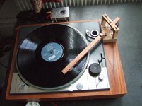
The design is for an 11 inch tonearm because I wanted to mount it on the plinth of the GL 75 turntable. Luckily I found the necessary specs on the wonderful Vinyl Engine site.(a Denon arm) I apologise for not reproducing them here, but I don't want typos spoiling this thread.
The basis of the arm is what I call a "cross-pivot", easiest to understand if you look at the diagrams and photos.
The diagrams in the attached PDF show the very basic principal that this arm utilises. The cross beam is suspended by 2 threads that cross, twist together(just one turn), and continue up to the bridge where they are secured. The bridge is positioned (Fig 3) so that the cross beam is suspended such that it would by gravity hang just forward (towards the tt centre spindle) of the vertical pin, but is hooked behind the pin. So the cross beam "leans" against the vertical pin.
MY CONSTRUCTION
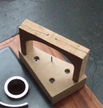
The first photo shows the mounting (mdf) consisting of the base, and the bridge. The crucial part is the small pin sticking up. For this I used a "nail" from a picture hanging bracket, hammered upwards through a just undersized hole in the bass. This is mounted at exactly the spindle to pivot distance from the arm specs, and it needs to be firm.
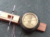
The second photo shows the underside of the arm. I made this from two, 3/4" strips of mahogany from my local wood yard, and a couple of little bits to mount the second crucial part: the cross beam. For this I used sewing needle, not quite ideal but it needs to be solid and a small diameter. Constant cross section is the ideal.
For the thread I used cotton(!) to start with, but I changed it to fishing line (4lb breaking strain. It is crucial that the thread is put on the cross beam so that when in exits the beam it does not touch other turns of the thread and it exits the forward side (the one that touches the vertical pin) This is really important. If you look carefully at the bridge you can see that the thread goes through 2 small holes. The tricky part is pulling each thread up the right amount to get the height right, and securing it. The 2 threads twisted together create a torque, and the direction of torque needs to be to assist anti skating. I used 2 pins mounted in the top for each and wrapped the thread many times round these before blutaking the thread down. It is difficult to take the weight of the arm whilst doing this. I found it best to do one at a time and adjust as necessary. For the counterweight I used a 2 oz and 4 oz weight from a kitchen scales, sellotaped (horror) to the arm. I bought the leads off the internet for a few pounds. For the tracking force I used the 1/4 oz weight blutaked on the top of the arm. The cartridge (Denon 103) is blutaked onto the arm. As I said very crude, but I had to compromise in order to make it. The geometry came from the Vinyl Engine site. The offset was done with a protractor and the null points were done with a home made protractor drawn on a piece of paper (surprisingly easy)
ASPECTS OF THE DESIGN
The design utilises pivots and as such there is very very little friction. The weight of the arm is taken by the bridge and is not grinding into the bearings.
Whilst it is very easy to make, it is very awkward to set up, and frankly I would not attempt this on a suspended deck.
There is a glaring flaw in the design in that the arm is free to move sideways at the pivot. However the dead weight of about 8 oz of the arm seems to make this disappear in practice. An attempt to move the arm sideways from the cartridge end shows how much force is needed. Also see footnote below.
My construction has no anti bias. I reasoned that a long arm needs it less, but it is a compromise. However there are several ways that one can build it in. The thread has torque that could be increased by widening the gap between the suspending holes, or moving the bridge sideways, so that the resultant force of the pin on the cross beam is off centre of the cross beam. Also possibly having the thread asymmetrically on the cross beam might have a similar effect.
Another problem is the horizontal rotation moves the touching point of the cross beam on the vertical pin. See Fig 4. This means that the anti bias changes in value as the arm moves across. In practice it is pretty negligible.
FOOTNOTE:The possible sideways movement at the pivot and the anti skating variation can both be addressed with the design of cross beam as shown in Fig 5, using a knife edge. (I will use a pencil sharpener blade if I ever try this) The contact point of the cross beam needs to have the same diameter. as the suspension points of the cross beam.
Although this explanation is quite long winded the design is actually very simple to make. The design works, and with access to a lathe (or some ingenuity that I can't think of) the Fig 5 design could be as good as any pivoted tonearm bar none.
Two more photos to follow.
Midrange
First of all I am sure that this will have been thought of before, and I know that you clever people will be able to tell me by who.
The design is for an 11 inch tonearm because I wanted to mount it on the plinth of the GL 75 turntable. Luckily I found the necessary specs on the wonderful Vinyl Engine site.(a Denon arm) I apologise for not reproducing them here, but I don't want typos spoiling this thread.
The basis of the arm is what I call a "cross-pivot", easiest to understand if you look at the diagrams and photos.
The diagrams in the attached PDF show the very basic principal that this arm utilises. The cross beam is suspended by 2 threads that cross, twist together(just one turn), and continue up to the bridge where they are secured. The bridge is positioned (Fig 3) so that the cross beam is suspended such that it would by gravity hang just forward (towards the tt centre spindle) of the vertical pin, but is hooked behind the pin. So the cross beam "leans" against the vertical pin.
MY CONSTRUCTION
The first photo shows the mounting (mdf) consisting of the base, and the bridge. The crucial part is the small pin sticking up. For this I used a "nail" from a picture hanging bracket, hammered upwards through a just undersized hole in the bass. This is mounted at exactly the spindle to pivot distance from the arm specs, and it needs to be firm.
The second photo shows the underside of the arm. I made this from two, 3/4" strips of mahogany from my local wood yard, and a couple of little bits to mount the second crucial part: the cross beam. For this I used sewing needle, not quite ideal but it needs to be solid and a small diameter. Constant cross section is the ideal.
For the thread I used cotton(!) to start with, but I changed it to fishing line (4lb breaking strain. It is crucial that the thread is put on the cross beam so that when in exits the beam it does not touch other turns of the thread and it exits the forward side (the one that touches the vertical pin) This is really important. If you look carefully at the bridge you can see that the thread goes through 2 small holes. The tricky part is pulling each thread up the right amount to get the height right, and securing it. The 2 threads twisted together create a torque, and the direction of torque needs to be to assist anti skating. I used 2 pins mounted in the top for each and wrapped the thread many times round these before blutaking the thread down. It is difficult to take the weight of the arm whilst doing this. I found it best to do one at a time and adjust as necessary. For the counterweight I used a 2 oz and 4 oz weight from a kitchen scales, sellotaped (horror) to the arm. I bought the leads off the internet for a few pounds. For the tracking force I used the 1/4 oz weight blutaked on the top of the arm. The cartridge (Denon 103) is blutaked onto the arm. As I said very crude, but I had to compromise in order to make it. The geometry came from the Vinyl Engine site. The offset was done with a protractor and the null points were done with a home made protractor drawn on a piece of paper (surprisingly easy)
ASPECTS OF THE DESIGN
The design utilises pivots and as such there is very very little friction. The weight of the arm is taken by the bridge and is not grinding into the bearings.
Whilst it is very easy to make, it is very awkward to set up, and frankly I would not attempt this on a suspended deck.
There is a glaring flaw in the design in that the arm is free to move sideways at the pivot. However the dead weight of about 8 oz of the arm seems to make this disappear in practice. An attempt to move the arm sideways from the cartridge end shows how much force is needed. Also see footnote below.
My construction has no anti bias. I reasoned that a long arm needs it less, but it is a compromise. However there are several ways that one can build it in. The thread has torque that could be increased by widening the gap between the suspending holes, or moving the bridge sideways, so that the resultant force of the pin on the cross beam is off centre of the cross beam. Also possibly having the thread asymmetrically on the cross beam might have a similar effect.
Another problem is the horizontal rotation moves the touching point of the cross beam on the vertical pin. See Fig 4. This means that the anti bias changes in value as the arm moves across. In practice it is pretty negligible.
FOOTNOTE:The possible sideways movement at the pivot and the anti skating variation can both be addressed with the design of cross beam as shown in Fig 5, using a knife edge. (I will use a pencil sharpener blade if I ever try this) The contact point of the cross beam needs to have the same diameter. as the suspension points of the cross beam.
Although this explanation is quite long winded the design is actually very simple to make. The design works, and with access to a lathe (or some ingenuity that I can't think of) the Fig 5 design could be as good as any pivoted tonearm bar none.
Two more photos to follow.
Midrange
Attachments
Midrange : great work. I love to see simple designs. Tell me is the vertical nail or pin in the base used only as a keeper of sorts to stop the arm from moving around too much? I am thinking that there is no contact between the pin and the arm under play conditions is that correct? I looks like you are using a multi strand filament or thread, have you tried mono filaments like fishing line or nylon or polyester. Those would provide a torsion as they would want o unwind at the twist much more than a stranded thread.
There was one thread suspended design on this forum some time back where the arm was suspended on a single tensioned filament (vertical) and the torsion of the filament as the arm tracked the record provided some anti skate force.
Thanks for posting. Best regards Moray James.
There was one thread suspended design on this forum some time back where the arm was suspended on a single tensioned filament (vertical) and the torsion of the filament as the arm tracked the record provided some anti skate force.
Thanks for posting. Best regards Moray James.
Hello Moray James. Yes, only contact is the permanent contact of the vertical pin and the crossbeam.
The photos were taken when I made the arm, and I have since changed the thread to nylon monofilament.
If you look at fig.3 (the dotted line is vertical) I hope it shows that the thread does not hang vertically. This is because the crossbeam (which is attached to the arm) is permanently displaced by the vertical pin in the direction away from the cartridge.. So the weight of the arm is permanently pulling the crossbeam against the pin. Thus, in answer to JN the arm CANNOT move in the direction of the cartridge.
Ok so the cross bar rolls around the pin. Seams logical then to think that the smaller the diametre of that vertical pin the better as that would result in a smaller range of motion around the circumference of the pin. Is that a reasonable and accurate assumption to make? If so then why not replace the pin with a highly tensioned thread? Thanks for posting, best regards Moray James.
PS: it has just occurred to me that it would be beneficial to place the position of the twist in the two threads at a nodal point along the straight line distance between the cross beam and the frame. Does that make sense to you? That ought to keep resonances to a minimum
PS: it has just occurred to me that it would be beneficial to place the position of the twist in the two threads at a nodal point along the straight line distance between the cross beam and the frame. Does that make sense to you? That ought to keep resonances to a minimum
Hello Moray James. Yes, only contact is the permanent contact of the vertical pin and the crossbeam.
The photos were taken when I made the arm, and I have since changed the thread to nylon monofilament.
If you look at fig.3 (the dotted line is vertical) I hope it shows that the thread does not hang vertically. This is because the crossbeam (which is attached to the arm) is permanently displaced by the vertical pin in the direction away from the cartridge.. So the weight of the arm is permanently pulling the crossbeam against the pin. Thus, in answer to JN the arm CANNOT move in the direction of the cartridge.
Last edited:
Hello midrange
That is an ingenious idea. I would concentrate on the knife edge version though. This could be the basis of a commercial high-end tonearm.
Congratulations!
Sincerely,
Ralf
That is an ingenious idea. I would concentrate on the knife edge version though. This could be the basis of a commercial high-end tonearm.
Congratulations!
Sincerely,
Ralf
Few years ago I thought of a similar design using string but with only on one side of the cross beam and add weight to that side. It was inspired by the Basis Vector design, a quasi-dualpivot arm with a secondary bearing to stabilize the torsional movement. Instead of the secondary ballbearing like the Vector, I can use a string from above the arm. And if the tie point can move up and down (or shortening or lengthening the string), it can change the azimuth. The Vector use an off-centered counterweight to make the arm lean on one side. I think you can simply add some mass to the side beam. Below is an example borrowing Midrange's picture, if you don't mind. I never built one so I don't know if it works or not. Another thing, if the crossbeam is placed at an angle like the headshell, say 23°, the vertical movement will not change azimuth microscopically.
Happy building!

Happy building!
Last edited:
Thanks for the responses. I am no expert so can only give limited replies.
Moray James; I agree that the thinner the vertical pin the less the movement of the contact point will be with the movement of the arm across the record. I am not sure to what degree in practice this is a problem. Any torque applied to the arm seems like a tiny % of what anti skating would be. The idea of a tensioned vertical thread instead of a pin seems good,(especially as the force acting on the thread from the crossbeam is only a small % of the weight of the arm) but a bit beyond my kitchen table capabilities. I think I would find the knife edge idea easier to make. Friction between the pin, (knife edge or thread) and the sideways movement of the crossbeam could be beneficial; some sort of non slip coating on the crossbeam perhaps. Although, again, I think the potential for horizontal movement at the bearing is more a theoretical problem than a practical one.
Directdriver; could you direct me to a diagram, or a self-explanatory picture of the principals of the Basis Vector arm. I found the written explanation at the manufacturer's site beyond my level of ability to visualise. Your idea of the single thread and counterweight on the crossbeam looks workable. Does it have the vertical pin? Could you explain how angling the crossbeam effects the azimuth variation at the cartridge. I can't grasp this.
Straight Tracker. Thank you for your kind words. I agree that the knife edge design (with the Fig 5 refinement in the crossbeam) is the most complete variation of this design, both in theory and practice. If anyone thinks it is worth making commercially, they are most welcome.
Yes I know that aspect of the design had been thought of before. It took me forever to think of crossing the threads, or filaments, without which my idea was a complete non-starter.
Directdriver; could you direct me to a diagram, or a self-explanatory picture of the principals of the Basis Vector arm. I found the written explanation at the manufacturer's site beyond my level of ability to visualize.
Below is the only picture I can find that shows the innards of the bearing. As you can see the main bearing is a unipivot spike with a ball bearing wrap around it. The majority of the mass rests on the spike but the ball bearing is there to stabilize the azimuth movement, something that leans on the ball bearing. The concept is similar to the Continuum Cobra and Copperhead tonearms.
An externally hosted image should be here but it was not working when we last tested it.
Your idea of the single thread and counterweight on the crossbeam looks workable. Does it have the vertical pin?
Yes.
Could you explain how angling the crossbeam effects the azimuth variation at the cartridge. I can't grasp this.
I should correct that it would affect the VTA. The cartridge is offset at an angle typically 23 degrees for 9 inch arm but the vertical bearing is place 90 degrees across the armtube and when the arm move up and down the VTA changes. Try to use a bent stick to simulate it and move up and down in exaggerated way and you will see the issue.
If you look at the horizontal bearings on a Rega arm they are offset at an angle. In a unipivot, the Graham is the only arm that offset the side weights because the designer has a patent on it.
Thanks for the thread and happy building!
Last edited:
Your idea of the single thread and counterweight on the crossbeam looks workable. Does it have the vertical pin? Yes. (I have not worked out how to use these quotation options.)
The practical/theoretical problem to overcome is that the supporting thread, and the pin need to occupy the same spot on the crossbeam. If there is a lateral displacement between the pin and the thread, as the arm turns around the pin the thread will no longer be vertical.
Quote:"The majority of the mass rests on the spike but the ball bearing is there to stabilize the azimuth movement, something that leans on the ball bearing."
I see it now. That is very clever.
Thanks for your responses.
- Status
- Not open for further replies.
- Home
- Source & Line
- Analogue Source
- My new "cross pivot" tonearm