I restrained myself from inserting a maniacal laugh in the title.
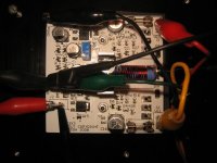
However, the amp is alive.
PCB: 76.2mm x 76.2mm or 3��x3���cuses as many surface mount components as possible.
I haven�ft power tested it yet, and it�fs getting kind of late to start that kind of thing�cbut the initial experiments are promising.
1. Check all resistor values with DMM.
2. Check all transistor polarities pin-out with DMM.
3. Check for power supply shorts with DMM.
4. Turn on with current limited supplies, ramp voltage slowly.
5. Adjust bias.
6. Apply input signal�camplifies. First time.
Not too bad...hi-res pics (I didn't post them here out of courtesy for the folks with low bandwidth connections...) at:
http://www.stuffscottbuilt.com/?p=107
After I do some testing under load...I'll get back with more details. The amp actually includes an overtemperature protection and SOA protection...should be fun to test...
Scott

Did some more testing this morning...
and I'm not sure I've got the bias compensation right. It's not exactly stable. It's good enough to prevent any kind of thermal runaway, but not good enough to keep the output stage at an optimum bias level.
Back to the simulations to see what I input wrong, or didn't model correctly.
If it's as simple as providing a higher mV/C correction that's easy...so hopefully it's the case.
As soon as I get Praxis running again (bad PS on that computer..) I'll post some distortion and frequency response plots.
Now I've also got to go build another one for some listening tests.....
Scott
Schematic...
It's a 3-stage Lin type topology. Fairly standard, with a few tweaks, differential pair with current sources/mirrors, VAS, dual pole compensation...CFP output etc...we've all seen the basic circuit before. (Self, Slone, Duncan...etc)
I've built larger versions of this circuit before, but this is the first time I've spent quite a bit of time optimizing the layout and component/circuit design for miniaturization. I had no clue how long that was going to take. I went through no less than 6 versions of the layout alone before I was satisfied enough to send off for PCBs...
Last time I built an amp with a similar circuit I couldn't actually measure the distortion with Praxis...it was below the floor of the system I have. I expect the same results this time...but I'll still post them when I get the chance.
So...anyone in the Austin area with an Audio Precision system that I could use?
Scott
- Status
- Not open for further replies.