So I thought I would share my experiences with these great drivers. Initially, I was trying to use the Neo8PDR with a pair of Seas TPXs in a simple two-way, crossing at around 800hz. The upper end peak in the Neo drove me crazy and it seemed all of the "fixes" took the life right out of it. That's what you get for trying to keep things simple.
So then, I read about the Neo3PDR here and got a couple, rolling off the Neo8 and adding in the Neo3. Much better but still peaky, still didn't gel. Sat on it for about a year and thought about it. Then, i read about removing the backs from the Neo3s and tried that - better. Next, I revisited my crossover, going to a full 3-way, 12 db slope, allpass. All I can say is what a difference a few components can make! I am currently rolling off the Neo8 at around 7khz and into the Neo3 - it has completely taken the edge off - talk about transients, talk about clean, talk about clarity, well, you get the idea.
I just want to say, for the money, if you spend a little time, these are great drivers! Now the mounting of them - well, that's something else. I bought some faceplates from Meniscus which fixed me right up but come on BG - how hard would it be?

Sorry for the double post, I lost my internet connection as soo as I pressed "submit" due to an area storm and didn't know if it went through.
I know this is an old post but I am looking on tips/advice on mounting Neo3's. Advice??? What I have realized though is the reason the Neo3's are hard to mount is because they are supposed to be hard to solidly lock down and torque the screws until the entire frame twists. which could and would happen if they had left holes like in the Neo8, "A more substantial driver"
Other than just going painfully slow and mounting one at a time. I have found no way to easily mount these in a "Line Source" configuration into hard Maple. And with #4 screws being the largest to fit in the slot this makes it quite difficult to fully run that tiny screw to depth before you spin out the drive head. With 24-26 Neo3's per side that is going to take awhile. So I guess I'll just pack a lunch.
Does anyone know the minimum distance between Neo3's in a line source config?. How about for Neo8 drivers for correct vertical wave dispersion? Is there a better wave guide config than the optional circular mount? If in a CBT array could you use a lesser amount? Are there any tricks to wiring up to 36, 4 Ohm Neo3's a line for a four ohm load?
We haven't seen your ideas for aligning those Neo 3 or perhaps Neo 8 drivers within your system. Typically, for line array/source use these planar drivers are stacked vertically to yield an long equivalent driver that covers both seated and standing listeners. Planar, ribbon, folded AMT, and other similar drivers are valued for their wide horizontal sound dispersion but longer rectangular drivers have vertical dispersion that trends to their height as frequency increases. Thus to get the sound coverage for a line array within in a listening space you need a vertical stack.
My Near Field Line Array White Paper covers aspects for using rectangular drivers in an array. I talk to how the driver radiation covers the overall vertical sound dispersion.
The Neo 3 overall height is 89 mm (3.5") while according to an on line drawing the active area of the driver is 35 mm wide by 49 mm high (that is 1.38" wide x 1.93" high). If we assume vertical mounting of the drivers, means that the ratio of the active area to overall height is 49 / 89 mm or 0.55 (55 %). While Neo 3s don't attain the 80% active coverage that I recommend, you likely will be pleased with them in your array. I'll assume that you mount the drivers with their frames touching to enable the active area to be its maximum. Bottom line is that you need to mount the Neo 3s as close as possible to achieve good results.
The impedance of the overall series and parallel arrangement of drivers can realized so that it can be amplifier friendly (say 4 to 8 ohms). I assume that you will be feeding the drivers with equal power levels. Examples of 4 ohms drivers is that 16 can be connected in 4 parallel strings of 4 in series to yield a 4 ohms impedance overall. For 25 4 drivers you can string 5 parallel lines of 5 drivers in series to attain 4 overall ohms. Likewise 36 4 ohms drivers in a 6 x 6 arrangement would be 4 ohms overall impedance.
http://www.audioroundtable.com/misc/nflawp.pdf
https://www.parts-express.com/pedocs/specs/264-714-bohlender-graebener-specifications-44393.pdf
Last edited:
...there are no pictures in this thread, so here are some...
Attachments
Instead of using screws, rout out a wide and shallow rabbet in the back of the baffle and use a healthy bead of adhesive caulk to fix the drivers in place.
Well, I tried to upload some pics so you could see what I am doing but the website isn't cooperating.
I am trying NOT to do what Tom is suggesting because until I feel I have it right, I want to be able to re-configure as needed. As a matter of fact I am doing that again today. I am actually overlapping the Neo3's at this point so that the distance from the bottom opening of slot on one to the top of the slot on the next tweeter is 0.84". I "could" overlap a bit more I guess. They are mounted on center to a "Bow" I've made, "1-inch wide" of maple with a radius of about 40'. They are mounted against a neoprene strip with a band around each end, top and bottom around the "bow". Total height is 8'-3". The sides of the Neo3's are 1" from the side of a line of twelve Neo8's. That line is flush with the baffle which is 23" wide using a 4" radius. But it is only 5 foot tall. Both lines of neo3 and neo8 extend to the full 8'-3". The baffle which extends to height with the Neo8's is 6" wide to the top The neo3's have no baffle after the 5 foot tall piece. There is also a separate cabinet that holds nine 8" woofers. I am using a servo corrected sub system "6" for 20hz-100hz. The woofer cabinet from 100hz to 750hx. The Neo8's from 750hz to 4.8khz and then the Neo3's 4.8khz and up.
The only thing I am not currently happy with is the imaging. Other than that they sound like nothing else I have ever heard.
I knew that phasing would be an issue but "was" going to solve that with an DSP system from accuton. Now I am not too sure. I am using a set of X-kitz, K-231 crossovers to get a five way system, "not cascaded".
I did post a few pics on "Audiogon" as a Virtual System. In case you want to look. And since I cannot use the system here to post pics.

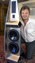
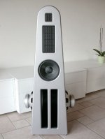
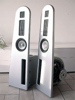
What you are doing is similar to several Christie Digital line array designs. The Christie Digital product line has multiple models that use their Neo 3 and 8 drivers in various configurations. All models use a line of 6 inch drivers with a line of planars (some models use the 3.5" Neo 3 unit while others use the Neo 8) spaced over the woofer line. Click on the various LA model links and you will see spec sheets of the configurations. Enlarge the drawings on the spec sheets to see the arrangement. Christie also has photos of the actual hardware on their web site.
Line Array Speakers | Christie - Audio Visual Solutions
I'm surprised that you are using the Neo 3 PDR mounting in your approach. That frame adds to the spacing between the tweeters which means you will have considerable high frequency response roll off for your array.
Line Array Speakers | Christie - Audio Visual Solutions
I'm surprised that you are using the Neo 3 PDR mounting in your approach. That frame adds to the spacing between the tweeters which means you will have considerable high frequency response roll off for your array.
Last edited:
Mock-up
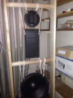
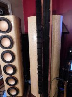
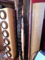
That's just one mock up I tried. I wasn't getting any good data on the Neo3's vertical dispersion. Just opinions. So I tried it with the mounting covers. It actually sounds ok but not quite what I was looking for. Here are a couple pics of what I am doing now. This configuration should get me at least 28 neo3 in the line. Overlapping is easier because of the radius. But not why there is a radius. When completed the tweeters will need to be on the outside edge to avoid a "shadowing", effect on the Neo8's. My only "real" worry is the phase. But since these are basically designed to be intimately adjustable, incrementally on all axis to a fine minutiae. Including the actual radius of the bow from it's center at ear height. distance from baffle, and a radial adjustment of +- 20 degrees. I think I'll be ok. This entire system is partly an exercise in isolation also. Each component is actually physically isolated through several means. As in the woofer cabinets for instance. There is a ring on which the driver mounts. Which isolates the transducer from the baffle. The baffle is completely isolated and decoupled from the base. The Base is isolated from the floor AND the box on the back holding the crossover.. And so on, and so on, throughout the system.
From what I have heard the actual vertical dispersion is basically nil. But again I have no real data and I am just beginning to test.
The first two pics show the "bow" and the tweeters mock mounted "15 so far", when I stopped last night. Something else making this challenging is the ohm load and power distribution. They are not all just Neo3's at 4 ohm. Same with the Neo8's. There are strategically located sets of the 8ohm, "PDR" and "S" models in there as well. The bass cab is still missing the top baffle piece, "Which is an open, one piece Corian baffle"which holds the top three woofers. At that point I was thinking of adding two or three of those new Accuton 8", "Perfect Center" woofers and may cross those a little
differently as well to smooth out the transitions on the 24db slope that I am using. And it looks like the pic uploader doesn't like me. I'll try later.
Thanks for the Info Jim!
That's just one mock up I tried. I wasn't getting any good data on the Neo3's vertical dispersion. Just opinions. So I tried it with the mounting covers. It actually sounds ok but not quite what I was looking for. Here are a couple pics of what I am doing now. This configuration should get me at least 28 neo3 in the line. Overlapping is easier because of the radius. But not why there is a radius. When completed the tweeters will need to be on the outside edge to avoid a "shadowing", effect on the Neo8's. My only "real" worry is the phase. But since these are basically designed to be intimately adjustable, incrementally on all axis to a fine minutiae. Including the actual radius of the bow from it's center at ear height. distance from baffle, and a radial adjustment of +- 20 degrees. I think I'll be ok. This entire system is partly an exercise in isolation also. Each component is actually physically isolated through several means. As in the woofer cabinets for instance. There is a ring on which the driver mounts. Which isolates the transducer from the baffle. The baffle is completely isolated and decoupled from the base. The Base is isolated from the floor AND the box on the back holding the crossover.. And so on, and so on, throughout the system.
From what I have heard the actual vertical dispersion is basically nil. But again I have no real data and I am just beginning to test.
The first two pics show the "bow" and the tweeters mock mounted "15 so far", when I stopped last night. Something else making this challenging is the ohm load and power distribution. They are not all just Neo3's at 4 ohm. Same with the Neo8's. There are strategically located sets of the 8ohm, "PDR" and "S" models in there as well. The bass cab is still missing the top baffle piece, "Which is an open, one piece Corian baffle"which holds the top three woofers. At that point I was thinking of adding two or three of those new Accuton 8", "Perfect Center" woofers and may cross those a little
Code:
Thanks for the Info Jim!
What I am doing
Hm, What I am doing "I guess" looks similar to what Christie Audio is doing. Their designs look like some JBL designs I've seen for commercial systems.
I did find out that they have an awesome sub "2 x 18" with dual 4" voice coils" on clearance. Continuous rating of 133dB SPL, But not sure I buy the 100dB sensitivity. If I get two, they may even get the squirrels to move from my attic.
I managed to find room for 29 tweeters so far, But I'll squeeze in a 30th.
On the left side HI/Mid cab in the pic I "set on", the inner baffle molding that looks purple without any finish yet, but it will look nice completed. "Costa Rica Mahogany".
It sounded much better yesterday when I had the Mid-Bass cabinet's inside instead of outside as they are in this pic. So those will get moved again today.
Hm, What I am doing "I guess" looks similar to what Christie Audio is doing. Their designs look like some JBL designs I've seen for commercial systems.
I did find out that they have an awesome sub "2 x 18" with dual 4" voice coils" on clearance. Continuous rating of 133dB SPL, But not sure I buy the 100dB sensitivity. If I get two, they may even get the squirrels to move from my attic.
I managed to find room for 29 tweeters so far, But I'll squeeze in a 30th.
On the left side HI/Mid cab in the pic I "set on",
the inner baffle molding that looks purple without any finish yet, but it will look nice completed. "Costa Rica Mahogany".It sounded much better yesterday when I had the Mid-Bass cabinet's inside instead of outside as they are in this pic. So those will get moved again today.
[/ATTACH][/ATTACH]
This is the current configuration, .864", between output slots on the Neo3s'.
Yeah, I know the wirings currently not to pretty but right now as I keep changing the wiring and mount config. I am not to worried about aesthetics at this point.
This is the current configuration, .864", between output slots on the Neo3s'.
Yeah, I know the wirings currently not to pretty but right now as I keep changing the wiring and mount config. I am not to worried about aesthetics at this point.
Attachments
What is the benefit of putting the tweeter array right over top of the midranges. I could do that with my 2.5 inch mids and a 40 inch line of pt-mini-6’s. I was going to put them very close to the edge of the mid speaker.
Well Christie did that, effectively splitting the wave which changes all your far-field effect numbers but it works. "Like allot of my own theories that do not follow atypical thought as diadem". What I'm doing is a bit different in that the tweeters are to the outside edge of the baffle, Partially shading the outside wave of the mid's. It causes a little diffraction of course, but sounds nice. I've studied Christies designs a bit. JBL's and others also. But I'm focused on home audio for 'lil ole me, not stadiums!
Have you ever tried building the tweeter line to the vertical length of your distance floor to ceiling? I was quite surprised the first time I did that as an experiment. It forms the wave quite differently then say a 40" line with an actual 96" or greater distance for the wave to expand in even with less than optimal spacing between transducer emission area's. When you do that, "40 inch line", your "of course" building a Point Source for that frequency range. I know that the "rule of thumb," is a minimum of 70% vertical coverage "actual emission coverage per driver", for line array "effect". But I find that this is not necessarily true in real world applications.
Have you ever tried building the tweeter line to the vertical length of your distance floor to ceiling? I was quite surprised the first time I did that as an experiment. It forms the wave quite differently then say a 40" line with an actual 96" or greater distance for the wave to expand in even with less than optimal spacing between transducer emission area's. When you do that, "40 inch line", your "of course" building a Point Source for that frequency range. I know that the "rule of thumb," is a minimum of 70% vertical coverage "actual emission coverage per driver", for line array "effect". But I find that this is not necessarily true in real world applications.
Have you ever tried building the tweeter line to the vertical length of your distance floor to ceiling?
I NEVER HAD that much money to burn.
Well, it wasn't that much to begin with. Everything goes on sale sometime and then there's "Buy a few here, buy a few next week...."
This IS my only hobby.
Hee hee "I could have bought a boat! A hole in the ocean you throw money into.
But then all that I would get to hear would be the waves....
This IS my only hobby.
Hee hee "I could have bought a boat! A hole in the ocean you throw money into.
But then all that I would get to hear would be the waves....
- Status
- Not open for further replies.
- Home
- Loudspeakers
- Planars & Exotics
- My Neo8/Neo3 Experience