Hi everyone
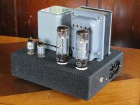
I just finished a pair of 5-20s. Although really 4-20s: the circuit follows the original Mullard schematic, except for the power supply, as is often done it seems. I used old Ferguson power transformers (repainted, with new dome nuts), in a bridge voltage doubler circuit, with two 220uF capacitors.
They seem to work nicely; there is nothing wrong with the way they sound, and frequency response was flat to within .2 dB 20-20000 Hz. And the output looks like the input.
But:
The DC voltages are all more or less the values that Mullard gives, except for the screen grid on the EF86. They say 153.5 V whereas I get 89 V. Given that the anode is at about 80 V, it seems that 153.5 V on the screen grid would be a bit high? I wonder whether there's a typo in the Mullard article. Or maybe someone could suggest what I should check (it's not the wrong value screen grid resistor!). At the moment, I'm tempted to assume that it's OK the way it is: what do you think?
Attachments
First rate construction!
I did some measurements a couple of years ago on input stage pentodes using RC bias of the screens. The tube to tube variability of the screen voltage is enormous! So... I probably wouldn't worry.
I did some measurements a couple of years ago on input stage pentodes using RC bias of the screens. The tube to tube variability of the screen voltage is enormous! So... I probably wouldn't worry.
The DC voltages are all more or less the values that Mullard gives, except for the screen grid on the EF86. They say 153.5 V whereas I get 89 V. Given that the anode is at about 80 V, it seems that 153.5 V on the screen grid would be a bit high? I wonder whether there's a typo in the Mullard article.
I think you're right. I can think of no reason for the screen voltage to be higher than the plate voltage.
Hi,
Usually better linearity may be a valid reason. In this regard there usually is no reason to have the screen voltage below anode voltage, if specs allow. Fortunately, pentodes are not (true) tetrodes, for which Ea > Eg2 is required because of early current takeover between them (or else massive distortion will occur).
Regards,
Tom
I think you're right. I can think of no reason for the screen voltage to be higher than the plate voltage.
Usually better linearity may be a valid reason. In this regard there usually is no reason to have the screen voltage below anode voltage, if specs allow. Fortunately, pentodes are not (true) tetrodes, for which Ea > Eg2 is required because of early current takeover between them (or else massive distortion will occur).
Regards,
Tom
OK, thanks for the advice (and thanks SY, I had hoped you might be listening!). I was slightly concerned that something might be slowly frying, it's good to know that this probably isn't the case.
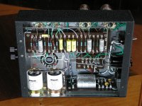
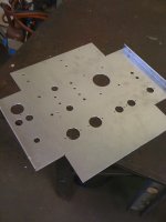
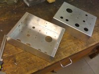
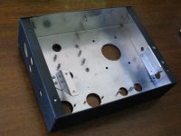
Here's some pictures of the chassis as it took shape: it's 2mm Al, the paint is a VHT wrinkle spray can (on a coat of etch primer). Someone I know TIGed the fillet welds down each edge at the corners.
I used PEM press-in studs, nuts and standoffs to hold it all together. If anyone else tries them, use a slightly smaller drill than they say and then they don't move out of place while you squeeze them in the vice! Unfortunately I only discovered this once I got to making the bottom covers.
Mark
Attachments
This answers a question of mine that I've had for a while. Every time I see those beautiful sheet metal diagrams in the Mullard handbook, I wonder if there were just a lot more hobbyists with floorstanding brakes in those days. And I wonder if anyone still does that anymore. You answered that in a most impressive way!
Here's why you don't worry about frying anything: the high voltage on the screen means it's drawing less current than nominal. The cathode resistor keeps the input tube from running away. Still, you might want to try a few other tubes to see if there's any difference in audible or bench performance. I did a bunch of 7199 and 6GH8 and the distortion spectra in a test circuit similar to your input stage were extremely inconsistent tube to tube, so I'd imagine that the same is true of EF86. If memory serves, the ones with the higher screen voltage did have cleaner distortion spectra.
Here's why you don't worry about frying anything: the high voltage on the screen means it's drawing less current than nominal. The cathode resistor keeps the input tube from running away. Still, you might want to try a few other tubes to see if there's any difference in audible or bench performance. I did a bunch of 7199 and 6GH8 and the distortion spectra in a test circuit similar to your input stage were extremely inconsistent tube to tube, so I'd imagine that the same is true of EF86. If memory serves, the ones with the higher screen voltage did have cleaner distortion spectra.
I envy those with a workshop suitable to crafting pieces like these. Nice work MarkT; your attention to detail is laudable. Even the wire-bundling shows old-world charm.
..Todd
..Todd
OK, thanks for the advice (and thanks SY, I had hoped you might be listening!). I was slightly concerned that something might be slowly frying, it's good to know that this probably isn't the case.
Here's some pictures of the chassis as it took shape: it's 2mm Al, the paint is a VHT wrinkle spray can (on a coat of etch primer). Someone I know TIGed the fillet welds down each edge at the corners.
I used PEM press-in studs, nuts and standoffs to hold it all together. If anyone else tries them, use a slightly smaller drill than they say and then they don't move out of place while you squeeze them in the vice! Unfortunately I only discovered this once I got to making the bottom covers.
Mark
Really Nice Work! I wonder where you get PEM stuff in the US.
Athos
the paint is a VHT wrinkle spray can (on a coat of etch primer)
Did you use the high temperature version or the regular one?
Thanks,
John
Answering Athos and John's questions:
The VHT paint was the high T one. (I would have preferred grey instead of black, but they don't make it anymore apparently.)
The PEM fasteners are American, so you should have less trouble getting them in the US than I did in Australia... pemnet.com lists some US distributors.
The VHT paint was the high T one. (I would have preferred grey instead of black, but they don't make it anymore apparently.)
The PEM fasteners are American, so you should have less trouble getting them in the US than I did in Australia... pemnet.com lists some US distributors.
- Status
- Not open for further replies.
- Home
- Amplifiers
- Tubes / Valves
- My Mullard 5-20: some photos and a question