Here is something different for a change:
It is a small, unassuming amplifier project, but with some unusual features:
It combines a circlo output topology with an active bias servo.
The servo stabilizes the quiescent current, but it goes further: it actively controls the output stage so that both sides always remain active in a "warm" class AB, having most of the attributes of the full class A, including a complete absence of crossover artifacts.
It is extremely easy to build, offers excellent performance even with 2N3055's, requires no adjustment, no matching, no thermal compensation and yet has a rock-solid thermal stability.
It is also incredibly healthy, and behaves gracefully, even with loads lower than 2R.
In short, a nice little amplifier, not in the top-class, but with excellent all round performances.
Meet the Circlophone©!!!
Attachments
It refers to the same-sex output transistors. It doesn't include the folklore of the original Circlotron, the floating supplies: it resembles more later versions, by Philips f.e., because there is no output transformer to worry about.Don't mind me asz-king, but what does the "Circlo" part refer to ?
The drive is similar to that of a circlotron, and the power supplies and transistors could be rearranged in a more familiar order, but there is no advantage to be gained, rather the contrary.
Member
Joined 2009
Paid Member
Here are some waveforms illustrating the operation and performances of the Circlophone©:
First, the output voltage together with the collectors currents of the output transistors: one can see that Ic never falls below ~75mA, and that the crossing current (Iq) is ~150mA (warm class AB).
Note that the "idle" transistor remains fully active: the active bias servo encompasses the whole amplifier from the input pair, and keeps all the transistors always active in a linear mode.
-
Next is the response to a 16V/10KHz squarewave on an infinite load impedance, followed by the same signal on a 3Ω load.
-
Then, there is a 16V/50KHz triangle wave, again on infinite and 3Ω loads.
Note: these pictures have been made with actual 2N3055's as output devices
Attachments

![10KHzInfini[1].JPG](/community/data/attachments/215/215170-b34a9b068e782a2791414def90c24a07.jpg?hash=s0qbBo54Ki)
![10KHz3ohm[1].JPG](/community/data/attachments/215/215177-bd5fdb5b79142fc5bb92b1e01786d185.jpg?hash=vV_bW3kUL8)
![50KHzInfini[1].JPG](/community/data/attachments/215/215185-c8397f15c84968bae49fd17ae1b595b1.jpg?hash=yDl_FchJaL)
![50KHz3ohm[1].JPG](/community/data/attachments/215/215190-97ad92ccbb247be47284b0146ebdf651.jpg?hash=l62SzLske-)


Here are some additional characteristics and information:
First the clipping behaviour, see picture.
It is shown with 20V supplies, the clipping occurs to within <1.5V of either rail.
It is a simulation, but the real life waveform is strictly identical.
The supply voltage can range from 15 to 40V with no or minor modifications:
The current through R21 should ideally be kept between 1 and 1.5mA, and the total voltage of the zeners should approximately match the supply voltage.
The input resistance is ~10K, but the source impedance is preferably kept below 1K, because of the base current modulation caused by the bias servo.
Output impedance is <3mΩ @1KHz
THD @1KHz and 0.9*Vmax is <0.005%
Full power bandwidth is >100KHz
Slew rate: positive ~24V/µs, negative ~20V/µs
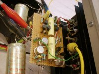
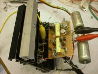
Here are some pics of one of the prototype:
First the clipping behaviour, see picture.
It is shown with 20V supplies, the clipping occurs to within <1.5V of either rail.
It is a simulation, but the real life waveform is strictly identical.
The supply voltage can range from 15 to 40V with no or minor modifications:
The current through R21 should ideally be kept between 1 and 1.5mA, and the total voltage of the zeners should approximately match the supply voltage.
The input resistance is ~10K, but the source impedance is preferably kept below 1K, because of the base current modulation caused by the bias servo.
Output impedance is <3mΩ @1KHz
THD @1KHz and 0.9*Vmax is <0.005%
Full power bandwidth is >100KHz
Slew rate: positive ~24V/µs, negative ~20V/µs
Here are some pics of one of the prototype:
Attachments
interesting circuit. Looks a bit like that one about
http://www.diyaudio.com/forums/solid-state/162644-siliconix-siemens-nmos-amplifiers-3.html
especially the circuit by post #23 and #24. The second differential stage by your circuit uses additional two zeners (at whole 24V) to avoid different C-E voltages by Q5 and Q6 (unfortunately without bypass capacitor in parallel). This step I miss by the previos mentioned schematic.
William T. Chater's approach uses a cascode solution at this place - go to
Bias control for power amplifiers
and to post #40 about
http://www.diyaudio.com/forums/soli...tter-audio-non-complements-audio-power-4.html
William T. Chater's approach for the bias servo unit looks also very intersting.
I don't understand the aim of follow devices in the schematic of post #1:
1) R26 and
2) R2
Last edited:
The increase in the collector voltage of Q5 due the zener's dynamic resistance is so tiny that it has no influence whatsoever, and requires no capacitor.interesting circuit. Looks a bit like that one about
http://www.diyaudio.com/forums/solid-state/162644-siliconix-siemens-nmos-amplifiers-3.html
especially the circuit by post #23 and #24. The second differential stage by your circuit uses additional two zeners (at whole 24V) to avoid different C-E voltages by Q5 and Q6 (unfortunately without bypass capacitor in parallel).
Improvements are certainly possible, the goal here is not to achieve top performances, but a good trade-off between performances and complexity.William T. Chater's approach uses a cascode solution at this place - go to
Bias control for power amplifiers
It is in fact quite different: Chater's system is sampled, whereas the Circlophone works in real time.William T. Chater's approach for the bias servo unit looks also very intersting.
This is of great importance, because the bias processor can correct in real time (at audio speed) the transfer function of the whole amplifier, in particular the crossover region.
This is what gives it its class A attributes.
See below the picture of the tail current of the input LTP: you can see that it is continuously varying to the rythm of the audio signal.
This explains why the THD figure is approximately 10x lower than for a traditional basic amplifier having a similar loop gain.
Also, Chater's system may work on paper, but in practice, this kind of scheme is fiendishly difficult to be made to work in reality.
Visch's topology is somewhat comparable, and it can easily be upset by real musical signals.
I don't understand the aim of follow devices in the schematic of post #1:
1) R26 and
2) R2
R26 breaks a possible short-circuiting path from supply to supply, and improves the overall RFI tolerance by adding damping in the path.
It increases the resilience of the design in case of "unexpected events".
It could be omitted, it has no active role.
R2 is part of the main lag/lead network compensating the common-mode loop formed by the bias processor.
Sorry, I don't do PCBs. Maybe you can do it 😉Looks very nice. Are you planning a PCB?
Attachments
I am replacing the livingroom lm3886 amp with a Dx Precision I. Was going to move the chipamp to the living room. But.... it already has high current regulated +-25V supplies in it so... I could replace that with this.
How about transistor substitution? I have a bunch of old power transistors, and new ones that were given to me or salvaged. I have about 10 of each 2SD1718A_S and 2SB1163A_S.
So if as long as the parameters in the datasheets are ok comparing between different transistors can I substitute some of these? I have tons of 2N5401/5551 as well.
Sorry, I don't do PCBs. Maybe you can do it 😉
That would make it number 26 on a list that grows almost daily !
Who knows, maybe one day...
Sure looks interesting though.
Regards,
Keith Arnold
Regulated supplies are a luxury which the Circlophone can do without.I am replacing the livingroom lm3886 amp with a Dx Precision I. Was going to move the chipamp to the living room. But.... it already has high current regulated +-25V supplies in it so... I could replace that with this.
How about transistor substitution? I have a bunch of old power transistors, and new ones that were given to me or salvaged. I have about 10 of each 2SD1718A_S and 2SB1163A_S.
So if as long as the parameters in the datasheets are ok comparing between different transistors can I substitute some of these? I have tons of 2N5401/5551 as well.
But it will work, of course.
This design has built-in component tolerance, and will happily accept almost anything you throw at it.
So far, the following types have been actually tested:
-Various brands of 2N3055's
-2N3772 Moto
-2N6259 STC
-MJ15024 Moto
-BDY58 ST
-BDX95 Philips
-BD183 Philips
-BD317 Tesla
-2SD424 EIC
-2SD555 NEC
.... and I am probably forgetting one or two more.
For Q5 and Q6, I have tried 2N3019, 2N2219, 2N1893, and I just checked with 2N5551, it also works, but I'm afraid they are a bit borderline: at 25V supply, the dissipation will be close to the 350mW abs. max. Pd.
The circuit is so tolerant, it will even work with fake or mismatched transistors, or even a different output configuration.
This is illustrated in the following pics:
The first shows what happens when everything that should be matched has been deliberately sabotaged: it still work perfectly.
The second has a darlington substituted for the CFP: the distorsion is bit up, but it remains pretty good.
There are some things to keep in mind, though:
The compensations have been optimized for 2N3055's, and if you use very different transistors, there might be some slight differences in the dynamic behaviour: with 2N3772 or 2N6259's, the slew rate is somewhat decreased.
Also, if you use fast (Ft>5MHz) transistors, the capacitor C11 shown as optional on the schematic becomes mandatory to remove local instabilities, and the circuit becomes more sensitive to the lengths of cable to the transistors.
Your 2SD1718 falls into that category, with an Ft=20MHz. It is pretty similar to the BDY58, which has been tested and works fine with C11 (without C11, there are low level VHF oscillations).
Also, a general remark, the value of C12 at 820pF is probably an overkill, and 180pF should normally be enough in practically all circumstances.
Finally, Q5 and Q6 should have a low enough collector capacitance, less than 15pF.
Most of the TO5/TO39's are suitable, including for the dissipation.
Attachments
Regulated supplies are a luxury which the Circlophone can do without.
But it will work, of course.
This design has built-in component tolerance, and will happily accept almost anything you throw at it.
So far, the following types have been actually tested:
-Various brands of 2N3055's
-2N3772 Moto
-2N6259 STC
-MJ15024 Moto
-BDY58 ST
-BDX95 Philips
-BD183 Philips
-BD317 Tesla
-2SD424 EIC
-2SD555 NEC
.... and I am probably forgetting one or two more.
For Q5 and Q6, I have tried 2N3019, 2N2219, 2N1893, and I just checked with 2N5551, it also works, but I'm afraid they are a bit borderline: at 25V supply, the dissipation will be close to the 350mW abs. max. Pd.
The circuit is so tolerant, it will even work with fake or mismatched transistors, or even a different output configuration.
This is illustrated in the following pics:
The first shows what happens when everything that should be matched has been deliberately sabotaged: it still work perfectly.
The second has a darlington substituted for the CFP: the distorsion is bit up, but it remains pretty good.
There are some things to keep in mind, though:
The compensations have been optimized for 2N3055's, and if you use very different transistors, there might be some slight differences in the dynamic behaviour: with 2N3772 or 2N6259's, the slew rate is somewhat decreased.
Also, if you use fast (Ft>5MHz) transistors, the capacitor C11 shown as optional on the schematic becomes mandatory to remove local instabilities, and the circuit becomes more sensitive to the lengths of cable to the transistors.
Your 2SD1718 falls into that category, with an Ft=20MHz. It is pretty similar to the BDY58, which has been tested and works fine with C11 (without C11, there are low level VHF oscillations).
Also, a general remark, the value of C12 at 820pF is probably an overkill, and 180pF should normally be enough in practically all circumstances.
Finally, Q5 and Q6 should have a low enough collector capacitance, less than 15pF.
Most of the TO5/TO39's are suitable, including for the dissipation.
Thank you for the information. I appreciate it. I'll see what I've got.
One or two details are still worth mentioning:
Since the structure of the circuit is highly symmetrical, both halves tend to "wake up" and "die" in a synchronous manner.
Residual asymmetries are taken care of by the bias processor, which forces a balance between the positive and the negative side.
Consequence?
There is inherently little or no power-on thump, without relay or additional circuitry.
(this doesn't mean that there will be no thump in a complete amplifier: if the preamplifier generates a thump after the amplifier has started, it will be amplified).
The virtual class A mode of operation is more than mere marketing words, and this is illustrated by the following:
Class B amplifiers normally have a substantial increase in THD when driving reactive loads, in particular inductive ones, whereas the THD of a good class A amplifier remains almost unaffected.
As shown below, the Circlophone© has its THD practically unchanged on a strongly inductive load.
Some more transistors have been (successfully) tried:
EP1926 Texas
BDY91 Philips
T-125 Solitron
SJ5135 Moto
41013 RCA
A word of warning for those attempting to simulate the circuit:
The DC and low frequency operation is fairly realistic, including the functioning of the bias processor, but the high frequency dynamic behaviour diverges completely:
In reality, the full power bandwidth easily exceeds 100KHz regardless what brand of 2N3055 is used, but the sim shows problems as early as 20KHz.
I don't know whether this is an inaccurate model problem, or a more fundamental limitation of LTspice.
Attachments
Elvee, nice circuit 
What happens if you use modern, faster devices like 2sc5200, instead of 2n3055 ?
What happens if you use modern, faster devices like 2sc5200, instead of 2n3055 ?
Sorry, I don't do PCBs. Maybe you can do it 😉
Interesting. It may have just gone on my list of designs to try. Don't get your hopes up too high though, it's a long list. 🙂
- Home
- Amplifiers
- Solid State
- ♫♪ My little cheap Circlophone© ♫♪