Hello, everyone.
It's been a while since I was on DIYAudio; as some of you may have guessed I sort of ran away from electronics as a result of my experiences here. But that is no one's fault but mine, and still then I wouldn't exactly say that I had the right mindset. I was recovering from ADHD and the darn medicine they give you for it, but I'm off the medicine now (of my own initiative) and can control my impulses. So, that said, I see no benefit in retracing the past so it's time to move on. It feels good to be back.
So at any rate, my original intention was to stop electronics until I could get a high school course; not so. After about two years, I decided I'd go back to biasing transistors to see if I could understand this vast concept. After that, I rediscovered electronics and my room has seen an incredible influx of what most people would call junk; On my computer desk sits another desk, on top of which I have recently been doing my electronic experiments. On it I have installed an oscillating fan, an ozone detector/ionizer, an artist's picture lamp (gives very good light!) an my Tektronix 561B oscilloscope (Am I lucky?). As I type his post I my keyboard is rocking back an forth on the piles of various dismantled objects underneath it; cheap ratchet screwdrivers, floppy drive innards, HDD armatures, PSU heatsinks. To the left of me sits a scanner optical receiver, staring me in the face. It has a solemn, absent look in it's eyes; I say, "Don't worry, I'll find a use for you, somehow..."
At any rate, I bought a butane microtorch and have been desoldering stuff for a while; I mainly go for the huge capacitors - they're handy when you've got a terrible power supply and you need something to smoothen out the ripple a bit.
Since my rediscovery, I have been experimenting mainly with simple amplifier designs and voltage regulators; Switchers work great but I've been looking into high-efficiency linear regulators. If it takes only about 2uA of current to turn on a pass transistor, how much current does linear regulation actually need?
So, first is first. In the line of amplifiers I was mainly thinking about he CFP emitter-follower, if that's what it's called. My reference texts are to be found on the Amplifier Institute site, upkept by Douglas Self. I thought about the original circuit, but made my own variation on the account of 'This is MY project - why should I build THEIR circuits?'. So, I changed the CCS a bit and added my own form of feedback. I discovered that the double-diode arrangement destroyed to output signal in terms of distortion, so I used the dual-transistor arrangement. What does cost matter when you have more than enough components on hand?
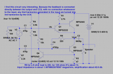
So, just so you know that I can, I'll explain to you the operation of the aforementioned CCS. R3 gives enough poer to turn on Q3, which in turn turns on Q4. Q4 clamps Q3's Vbe to the just-conducting point because any excess current from Q3's emitter opens up Q4 and causes it to leak current away from Q3's base. So given that there is enough power from R3, both transistors will turn on and R3 and Q4 will work as a voltage divider to keep Q3 at just-conducting. This effectively biases Q4 as well, so there should be about 600mV voltage drop across R2; so we can compute the output current of the CCS by 0.6/47=about 12mA.
As you can see, Q1 is high-beta; you my also notice the enormous input an output capacitors. I'll save that for later. R8 and C4 form the feedback network; with this configuration C3 and the feedback network form a differential network that supplies Q3 with any difference in their signal, which will cancel out distortion by leaking that error from Vout. This idea came of the fact that I, with much grief discovered that this CCS formation was not impervious to supply voltage fluctuations. However, the circuit was designed to be linear, with it's own feedback in the form of Q4 - so if his circuit is linear, why not use it or feedback? See, I'm a genius. Not really. But you get the picture. As you can see on the diagram, I have some notes; the one at the top expresses the problem with 2nd harmonics in the input being turned into 3rd harmonics by the feedback. I figured this wasn't a serious problem as long as Q1 was biased sensibly. R3 isn't the usual 22k because I found that the circuit for some odd reason would simply not start with higher values (???).
At any rate, the diagram is attached; I've built this one (yes, I have) and have tested it a bit; a square wave from my oscilloscope's calibration unit displays perfectly with no rolloff except for when I connect the speaker.
A quick 50mS simulation of the exact circuit diagrammed gives slightly above 10mA peak-peak output and about 0.035% THD.
If all goes well with this circuit, I'll post my linear regulator circuit which I plan to build to test as well.
- keantoken
It's been a while since I was on DIYAudio; as some of you may have guessed I sort of ran away from electronics as a result of my experiences here. But that is no one's fault but mine, and still then I wouldn't exactly say that I had the right mindset. I was recovering from ADHD and the darn medicine they give you for it, but I'm off the medicine now (of my own initiative) and can control my impulses. So, that said, I see no benefit in retracing the past so it's time to move on. It feels good to be back.
So at any rate, my original intention was to stop electronics until I could get a high school course; not so. After about two years, I decided I'd go back to biasing transistors to see if I could understand this vast concept. After that, I rediscovered electronics and my room has seen an incredible influx of what most people would call junk; On my computer desk sits another desk, on top of which I have recently been doing my electronic experiments. On it I have installed an oscillating fan, an ozone detector/ionizer, an artist's picture lamp (gives very good light!) an my Tektronix 561B oscilloscope (Am I lucky?). As I type his post I my keyboard is rocking back an forth on the piles of various dismantled objects underneath it; cheap ratchet screwdrivers, floppy drive innards, HDD armatures, PSU heatsinks. To the left of me sits a scanner optical receiver, staring me in the face. It has a solemn, absent look in it's eyes; I say, "Don't worry, I'll find a use for you, somehow..."
At any rate, I bought a butane microtorch and have been desoldering stuff for a while; I mainly go for the huge capacitors - they're handy when you've got a terrible power supply and you need something to smoothen out the ripple a bit.
Since my rediscovery, I have been experimenting mainly with simple amplifier designs and voltage regulators; Switchers work great but I've been looking into high-efficiency linear regulators. If it takes only about 2uA of current to turn on a pass transistor, how much current does linear regulation actually need?
So, first is first. In the line of amplifiers I was mainly thinking about he CFP emitter-follower, if that's what it's called. My reference texts are to be found on the Amplifier Institute site, upkept by Douglas Self. I thought about the original circuit, but made my own variation on the account of 'This is MY project - why should I build THEIR circuits?'. So, I changed the CCS a bit and added my own form of feedback. I discovered that the double-diode arrangement destroyed to output signal in terms of distortion, so I used the dual-transistor arrangement. What does cost matter when you have more than enough components on hand?
So, just so you know that I can, I'll explain to you the operation of the aforementioned CCS. R3 gives enough poer to turn on Q3, which in turn turns on Q4. Q4 clamps Q3's Vbe to the just-conducting point because any excess current from Q3's emitter opens up Q4 and causes it to leak current away from Q3's base. So given that there is enough power from R3, both transistors will turn on and R3 and Q4 will work as a voltage divider to keep Q3 at just-conducting. This effectively biases Q4 as well, so there should be about 600mV voltage drop across R2; so we can compute the output current of the CCS by 0.6/47=about 12mA.
As you can see, Q1 is high-beta; you my also notice the enormous input an output capacitors. I'll save that for later. R8 and C4 form the feedback network; with this configuration C3 and the feedback network form a differential network that supplies Q3 with any difference in their signal, which will cancel out distortion by leaking that error from Vout. This idea came of the fact that I, with much grief discovered that this CCS formation was not impervious to supply voltage fluctuations. However, the circuit was designed to be linear, with it's own feedback in the form of Q4 - so if his circuit is linear, why not use it or feedback? See, I'm a genius. Not really. But you get the picture. As you can see on the diagram, I have some notes; the one at the top expresses the problem with 2nd harmonics in the input being turned into 3rd harmonics by the feedback. I figured this wasn't a serious problem as long as Q1 was biased sensibly. R3 isn't the usual 22k because I found that the circuit for some odd reason would simply not start with higher values (???).
At any rate, the diagram is attached; I've built this one (yes, I have) and have tested it a bit; a square wave from my oscilloscope's calibration unit displays perfectly with no rolloff except for when I connect the speaker.
A quick 50mS simulation of the exact circuit diagrammed gives slightly above 10mA peak-peak output and about 0.035% THD.
If all goes well with this circuit, I'll post my linear regulator circuit which I plan to build to test as well.
- keantoken
Attachments
Helloes again.
I'm guessing by the way no one replied that I either did or said something stupid or ignorant, and people just don't want to spend the time to tell me how much of a failure my circuit is, or my endeavors are not entirely failures and they just have more interesting things they want to do.
Of course, if I simply wrote so much that no one wanted to bother reading, please tell!
Either way, I would at least like someone to point out which. I won't get overly frustrated if many of my ideas turn out not all that great; I'm still learning.
At any rate, I remember getting a few reply notification emails, but the posts were gone by the time I reached the thread.
two years ago, all my threads used to get ignored; I'm hoping that I can reverse that.
Now I do understand that using the CCS as as means of feedback somewhat defeats its purpose, which is to keep steady bias for the input transistor. But I would think that since it is feedback, the distortion would be clamped out anyways. Any follow-ups?
- keantoken
Maybe no one replied because no one can accept an amplifier trying to feed a 8ohm speaker with a pair of mpsa42/92?
How did you determine input impedance? It's more likely to be ~2k, far away from 1 mega ohm. What is r6?
Mike
How did you determine input impedance? It's more likely to be ~2k, far away from 1 mega ohm. What is r6?
Mike
Oh, R6 is a dummy. Should've clipped it out. I put it in as a quick 'n crappy impedance fix for my own computer soundcard. I also probed the output in parallel with a 10-ohm resistor so that I could look at it on my oscilloscope and then through my soundcard input. I would guess you're right in saying that trying to feed an 8-ohm speaker is pretty pathetic.
Really all I wanted with this circuit is something that I could feed input and actually get sound out of. And it worked, too. I built it and looked at various waveforms generated by my soundcard. There were obvious 2nd harmonics, as I could see with saw waves and a few variations I made myself.
About the transistors used, they were really all I had. For some reason I ended up with a bunch of MPSAs somewhere.
I could actually hear sound if I put a good speaker on it, and it got decently loud, but too much input and it distorts horribly. As far as I'm aware, a good amp will work flawelessly up until the point the input or other devices start clipping. Not so in this one, I would need more extensive feedback.
I determined input impedance by taking the input voltage and dividing it by the current through C1 since R6 essentially didn't do anything.
- keantoken
Everybody learns differently. I don't know the best method for you, but I need a mixture of hands-on and good books. The books have to be very practical- the mathematical nightmares often used for textbooks these days are worthless if you don't have that background. At a minimum, one should have (and read) Jung's op-amp cookbook, Horowitz & Hill, and Doug Self's book on power amps. Barnstead's Circuit Analysis is a good reference, and one should read every analog application note, magazine article, and column written by Jim Williams, Bob Pease, Walt Jung, and a few others. Fortunately, much of it is on-line. Most used book stores will have some decent Intro to EE textbooks from the '40s on. These are surprisingly useful. IMO, a simulator is a dangerous thing, because it lets you forget about the limits of real world parts. It will let you build a 100W amp out of some TO-92 transistors, if you so choose. I see too many people trying to design/build multi-transistor feedback amplifiers, when they should be concentrating on how to correctly bias a single device, and maybe get really cozy with ohms law. People here quickly learn to say, "oops, this one skipped the fundamentals, best to move on rather than get tangled in a futile discussion".
I try to use the simulator sensibly, going with practical resistance values and such. The thing is, I read fundamental electronics books, and don't find anything I don't already know. And then for some reason I find out that my circuits are basically crap. Very strange. But I'll take what you say into account. About the application notes, it shouldn't be hard to find those.
I just went to a bookstore a few days ago and picked out all the books that I could find. I also found one titled 'Elements of Transport Phenomena'. I'm not sure what that is, as I've not looked it up yet, but I tkok a peak inside and it looked like it was related to semiconductor physics somewhat, so I got it too.
- keantoken
- Status
- Not open for further replies.
- Home
- Amplifiers
- Solid State
- My latest circuits