First of all I want to thank Elso for sharing his project.
Of course my implementation doesn't claim to be state of the art, since it's made on veroboard without a great experience on HF layout, but I thought it could be nice to share my building experience and to receive a feedback from who has built it (and from Elso, of course!).
I borrowed (again 😉 ) a digicam and took a few shots.
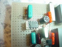
Pic 1: the assembly
Of course my implementation doesn't claim to be state of the art, since it's made on veroboard without a great experience on HF layout, but I thought it could be nice to share my building experience and to receive a feedback from who has built it (and from Elso, of course!).
I borrowed (again 😉 ) a digicam and took a few shots.
Pic 1: the assembly
Attachments


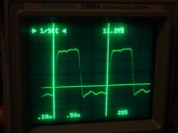
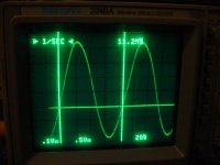
Last pic.. voltage at source of Jfet.. can someone explain why the waveform has a bump?
Should I try swapping the fet with another model or I'd better change the value of the source resistor (or what else)?
Cheers
Andrea / waiting for comments
Should I try swapping the fet with another model or I'd better change the value of the source resistor (or what else)?
Cheers
Andrea / waiting for comments
Attachments

to bump or not to bump...
While taking further measurements to get rid of this bump I noticed the extreme sensitivity of the node connected to the source to capacitive loading to ground... I should have realized that before (the cap to gnd is only 39 pF !) but all became clear whan I left out the cap and connected my oscilloscope probe (10x)... I got a nearly perfect sinewave!
Then connected the same probe to the output and.. nothing! The oscillator had stopped working...
Conclusion: the bump is probably due to the capacitance of the probe
Cheers
Andrea / who enjoys learning from building circuits😀
Kwak-clock
Hello Andrea,
You got decent squarewaves indicating a working clock. The "bumps" you mentioned are not important at all.
One of my first faults was connecting a 1x probe to a CMOS oscillator as it stopped working immediately. Yes ordinary probes have capacitance too.
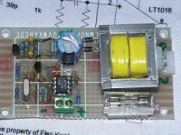
I am using other kind of parts but I have seen pictures of the KC with all kinds of parts. Here is another one (not by me)😎
Hello Andrea,
You got decent squarewaves indicating a working clock. The "bumps" you mentioned are not important at all.
One of my first faults was connecting a 1x probe to a CMOS oscillator as it stopped working immediately. Yes ordinary probes have capacitance too.
I am using other kind of parts but I have seen pictures of the KC with all kinds of parts. Here is another one (not by me)😎
Attachments
Hi,
I'm just finishing mine on vero board ,too.Had put it together week ago but waited for J309 to arrive (thanks Elso for J309,i just recived it a couple of hours ago).
I'm just not qiute sure how the pin-out of J309 is and how to put it into circuit.
I assume drain goes to + supply,source to crystal and gate to AD8651 and to ground trought 1Kohm resistor.
Is it correct??
Bartek
Pinout
Hello Bartek,
See this site for pinouts by Yeo :http://www.diyparadise.com/clock.html
It is Drain to supply, Source to 1k and Gate to crystal.😎
zygibajt said:Hi,
I'm just finishing mine on vero board ,too.Had put it together week ago but waited for J309 to arrive (thanks Elso for J309,i just recived it a couple of hours ago).
I'm just not qiute sure how the pin-out of J309 is and how to put it into circuit.
I assume drain goes to + supply,source to crystal and gate to AD8651 and to ground trought 1Kohm resistor.
Is it correct??
Bartek
Hello Bartek,
See this site for pinouts by Yeo :http://www.diyparadise.com/clock.html
It is Drain to supply, Source to 1k and Gate to crystal.😎
Thanks a lot.
Maybe i will put some photos tomorrow if I get the camera.
For now I will use it with CDP supply but will build separate this coming week.
Bartek
Maybe i will put some photos tomorrow if I get the camera.
For now I will use it with CDP supply but will build separate this coming week.
Bartek
Re: Kwak-clock
Hello Elso,
do you think that a separate power supply is worthwhile or i can sticjk with the one of the CDP?
Cheers
Andrea
Elso Kwak said:Hello Andrea,
You got decent squarewaves indicating a working clock. The "bumps" you mentioned are not important at all.
One of my first faults was connecting a 1x probe to a CMOS oscillator as it stopped working immediately. Yes ordinary probes have capacitance too.
I am using other kind of parts but I have seen pictures of the KC with all kinds of parts. Here is another one (not by me)😎
Hello Elso,
do you think that a separate power supply is worthwhile or i can sticjk with the one of the CDP?
Cheers
Andrea
Re: Re: Kwak-clock
Hi Andrea,
I tried both but found the raw supply of the player giving better sound. This is a rather unexpected result but I can live with that. Just follow the instructions I have sent you.
😎
Andypairo said:
Hello Elso,
do you think that a separate power supply is worthwhile or i can sticjk with the one of the CDP?
Cheers
Andrea
Hi Andrea,
I tried both but found the raw supply of the player giving better sound. This is a rather unexpected result but I can live with that. Just follow the instructions I have sent you.
😎
I Just wondering..
HI. Elso Kwak
I wanna make your KWAK-CLOCK-7
But I wanna use different PSU
I think high quality SHUNT REGULATOR will be fine
So I have to design SHUNT REG for KC7
But I dunno how much current needed for Oscillation(J309 and etc..) section. For AD8561(AD8611) section I can refer to Datasheet 😕
Would you tell me how much current needed at oscillation section(J309) 😉
Sorry for poor English
Merry Christmas !!
Hello,
thanks to Elso for sharing his knowledge.
I am looking around for the components, j309 seems to be difficult to buy. J310 is no problem here, so can I use this without
any problems?
Can anyone please name the thread where Elso postet the schematic for Elso Kwak 7, I downloaded the schematic, but missed to save the url. I wouzld like to link it at my website.
Thanks to all
Christian.
- Status
- Not open for further replies.
- Home
- Source & Line
- Digital Source
- My Kwack clock implementation