Hi Eva,
is that -6db output equivalent to 25W into 4ohm or 50W into 4ohm.
Would the square wave stress the output stage even less because the devices see either low Vce or low Ic and rarely feel the effect of combined IV that the sine wave causes.
But back to 50W into 4ohms, that's hardly a severe test for a pair of 150W devices.
I like your cooling caveat.
Hi Eva,
I said
I did not say it would release the magic smoke, but my statements are fair warning of impending doom.
I said
and then went on to say100W at a phase anle of 45degrees is right on the 100mS SOAR at Tc=35degC.
I could not recommend that for any DIYer
I did not say it would release the magic smoke, but my statements are fair warning of impending doom.
AndrewT said:Hi Eva,
is that -6db output equivalent to 25W into 4ohm or 50W into 4ohm.
Would the square wave stress the output stage even less because the devices see either low Vce or low Ic and rarely feel the effect of combined IV that the sine wave causes.
But back to 50W into 4ohms, that's hardly a severe test for a pair of 150W devices.
I like your cooling caveat.
A square wave at -6dB (an amplitude of 50% rail voltage) yields the worst-case absolute maximum amplifier dissipation when driving any resistive load (the output stage dissipates as much power as it outputs).
I originally intended that amp to run at 42V rails with a max output of about 60 watts into 8 ohms and 100 watts into 4. I cranked the voltage up to 50 volts just to see how the amp would perform, and it really held up well into an 8 ohm resistive load up to 100 watts. But without further testing I can't recommend running the amp into a reactive load at high output levels with 50V rails. But for 60watts into 8 ohms, and 100watts into 4 ohms the higher rails improve THD. Here's what I measured:
At 50V rails: H2 = -84.2db, H3 = -86.1db, H4 and beyond measures well below -90db.
At 42 rails: H2 = -76.5db, H3 = -83db, H4 and beyond still below 90db.
At 50V rails: H2 = -84.2db, H3 = -86.1db, H4 and beyond measures well below -90db.
At 42 rails: H2 = -76.5db, H3 = -83db, H4 and beyond still below 90db.
Hi Andrew,
This is the link to that amp which uses 4 pairs of Toshiba Transistor 5200/1943 pair..
http://www.audioplus-india.com/product.asp?pid=399&bid=7&mgid=7
The only protection I have seen in that amp is a Series Resistor 0.05 OHMS in the output is used to sense the current through it...No other type of VI limiting was applied....
Still this amp is happy in driving 4 ohms reactive loads.....
regards,
K a n w a r
Hi Kanwar,
thanks for taking the time to look out that info.
Your example appears very similar to an amp I bought just to see how a CHEAP commercial high power stage is put together. It also has 4 pair 2sa1943/c5200 running on +-93Vdc.
This one claims 350W into 8r and 525W into 4r. It does not specify if continuous.
I do not dare testing it to prove their claims are accurate for fear of blowing it up.
A Polish PA amplifiers from "LDM" are drwing 800W from 4 pairs of these toshibas without problems. These are realy powerful and modern devices for relatively cheap.
There are several keys to understand why the transistors doesn't blow:
- Each bank of output devices is only used half of the time and rests happily idle during the other half.
- Music signals only ask for maximum amplifier dissipation periodically and with a quite low duty factor, maybe between 1/5 or 1/10.
- Even a 50Hz bass note only aksks for high transistor dissipations during 3 or 4 miliseconds in each cycle and for each bank, within a total 20ms period. 100ms SOA is not likely to be the rule that applies in these circumstances.
- The non-flat frequency response of our hearing forces most of the power content of music signals to be below 500Hz where average loudspeaker impedance is usually higher than nominal due to resonance. Also, the delicate nature of our hearing above 500Hz prevents heavy power contents there (at least most of the time).
- Phase shift in loudspeakers always comes together with increased impedance, furthermore, it's always a sign of impedance roll-off, so for example, to get 45 degrees lag though an inductor, impedance *must* have increased by 3dB. Thus natural loudspeaker reactiveness usually produces less output stage stress than a plain resistive load, yielding the usual reactive SOA calculations pointless (except when the crossover is passive and badly designed). Some crossover and LCR resonator impedance and phase simulations may be useful to understand that (one of the worst passive crossover design practices is to use a very high Q LCR -where R is very low- to boost or cut output from a particular driver in a particular frequency range without caring about the resulting impedance).
Hi Eva,
I follow your argument and agree with the bulk of it.
However, I need to ask a few questions prompted by it.
This is confirmed in an ESP discussion on minimum reactive impedances but ESP was not as eloquent as you.
Now my area of disagreemnt.
We agree that the major part of the voltage/energy element of the wideband signal is at low frequency. But why stop at 50Hz? There are many signals below this frequency and at least in film sound tracks becoming more common, when they do occur they tend to be sustained. If you use digital sources, more sound producers (the people) are using very low frequencies for sound effect. Based on this, I will use as an example a sustained 10Hz signal that due to our reduced hearing ability (almost zero) could be very large compared to the remainder of the sound track. The output devices see this signal on alternate half cycles so they get a rest (agreed) but the manufacturer quotes all the short term SOA values for single shot events and many warn against repetitive signals.
The 10Hz signal half cycle lasts 50mS, but the device sees more than 50% energy for about 60% of this (about 30ms). With a reactive load this becomes worse and the high energy part of the cycle extends outwards towards 40mS and repeats every 100mS (that's a rest period, while dissipating some energy, of about 60mS). On the basis that the repetition is a major factor in device failure then I do not think that even the 100mS SOA is a safe one to use. I will tend towards using the DC values to be safe.
Now reverting to your figures;
What do other designers think?
In the recent past I have, possibly mistakenly, assumed that the reactive load increases energy disspation in the output devices and I look forward to hearing views on this.
I follow your argument and agree with the bulk of it.
However, I need to ask a few questions prompted by it.
Based on the above statement which sounds "right" then the minimum reactance at 45degree phase angle is the DCR plus the reactance causing the phase angle. Have I read you correctly?to get 45 degrees lag though an inductor, impedance *must* have increased by 3dB
This is confirmed in an ESP discussion on minimum reactive impedances but ESP was not as eloquent as you.
Now my area of disagreemnt.
We agree that the major part of the voltage/energy element of the wideband signal is at low frequency. But why stop at 50Hz? There are many signals below this frequency and at least in film sound tracks becoming more common, when they do occur they tend to be sustained. If you use digital sources, more sound producers (the people) are using very low frequencies for sound effect. Based on this, I will use as an example a sustained 10Hz signal that due to our reduced hearing ability (almost zero) could be very large compared to the remainder of the sound track. The output devices see this signal on alternate half cycles so they get a rest (agreed) but the manufacturer quotes all the short term SOA values for single shot events and many warn against repetitive signals.
The 10Hz signal half cycle lasts 50mS, but the device sees more than 50% energy for about 60% of this (about 30ms). With a reactive load this becomes worse and the high energy part of the cycle extends outwards towards 40mS and repeats every 100mS (that's a rest period, while dissipating some energy, of about 60mS). On the basis that the repetition is a major factor in device failure then I do not think that even the 100mS SOA is a safe one to use. I will tend towards using the DC values to be safe.
Now reverting to your figures;
A repetion of 20ms implies a rest period of about 16mS. But even that 16mS rest period is arguable, for 50Hz the rest period could be as little as 12mS. This hardly warrants single shot status and seriously compromises the suggestion that50Hz bass note only asks for high transistor dissipations during 3 or 4 miliseconds in each cycle and for each bank, within a total 20ms period
unless you meant using DC SOA, but I believe you are saying that a shorter time than 100mS is the appropriate value to use. I do not think we will ever agree on this. I am still listening, convince me.100ms SOA is not likely to be the rule that applies in these circumstances.
What do other designers think?
In the recent past I have, possibly mistakenly, assumed that the reactive load increases energy disspation in the output devices and I look forward to hearing views on this.
Sorry to interupt your conversation, I just wanted to know if this is an amplifier with very good sound quality.
Let me explain:
I'm looking for an amplifier to built, with very good sound quality. I don't care for power. Even if it's let's say 5 watt, I care only for sound quality.
I was thinking in building one with tubes, but I'm not sure if it worths the trouble.
What do you think?
Let me explain:
I'm looking for an amplifier to built, with very good sound quality. I don't care for power. Even if it's let's say 5 watt, I care only for sound quality.
I was thinking in building one with tubes, but I'm not sure if it worths the trouble.
What do you think?
We are almost blind if we try to design amplifiers without knowing well the load. I strongly recommend messing with speakers to anybody whose mind is focused on amplifiers only. I have randomly picked the following impedance plot from google, it characterizes quite well the impedance and phase versus frequency curves of any small or medium sized vented two-way loudspeaker with a 6.5" or smaller woofer. For larger bass drivers with lower Fs and port tunings, the 20Hz to 200Hz segment of this plot may be shifted down by up to an octave.

BTW: The impedance curves from sealed enclosure subwoofers are even funnier because they show a 20 to 200 ohm wide peak centered in the 30Hz range. At least, in vented enclosures the resonance peak is flattened by the resonator load.
BTW: The impedance curves from sealed enclosure subwoofers are even funnier because they show a 20 to 200 ohm wide peak centered in the 30Hz range. At least, in vented enclosures the resonance peak is flattened by the resonator load.
Hi aetosa,
It's in excellent sounding amplifier. I'd love to have several fanatics like myself out here try it out, compare it some other kits. I don't have any boards at the moment but should have some in early may, but I'd be glad to order more if people are interested. Just let me know, and I'll add you to the list. I'm also working on a 100 watt version with four output transistors. The boards arrived yesterday so hopefully have them up running sometime next week.
aetosa, I'll email you when they arrive. Thanks for the interest.
Best regards,
Al
If you mean PCB, I think you've published it in the beggining of your post.
I'll make it from there. If I won't make it, I'll let you know.
I'll make it from there. If I won't make it, I'll let you know.
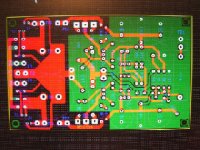
aestosa, here's a pic of the board. Green being the top layer, red bottom. It's not the greatest image but hopefully it's enough to get you started. I'll post shortly a new schematic with part numbers that match the silk. Let me know if you need anything else. You'll be amazed how great this little amplifier sounds.
Best regards,
Al
Best regards,
Al
Attachments
Hi Leolabs,
I guess you mean why not try a Darlington VA stage. I understand the advantages from a design stand point but in IMO sonically it makes no difference. And my objective all along was to build a simple amp with a low parts count with great stability, that sounds great. The low parts count allowed room on the board for high end components that are normally large like Black Gates, Nichicon, Auricap caps to fit on a small board.
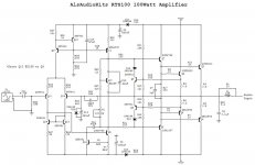
I tried many different circuits, starting with the schematic below with two output transistors instead of four, and many variations of it. I tried symmetrical versus non symmetrical. In the end the KLA circuit sounded best to me and my three test subjects.
I've tried this circuit before with an external power supply and it didn't sound nearly as good. I think the magic from this little amp comes from placing the AC filter power supply caps on board, and possibly from the amps top side ground plane.
Has anybody out here tried a similiar layout?
I guess you mean why not try a Darlington VA stage. I understand the advantages from a design stand point but in IMO sonically it makes no difference. And my objective all along was to build a simple amp with a low parts count with great stability, that sounds great. The low parts count allowed room on the board for high end components that are normally large like Black Gates, Nichicon, Auricap caps to fit on a small board.
I tried many different circuits, starting with the schematic below with two output transistors instead of four, and many variations of it. I tried symmetrical versus non symmetrical. In the end the KLA circuit sounded best to me and my three test subjects.
I've tried this circuit before with an external power supply and it didn't sound nearly as good. I think the magic from this little amp comes from placing the AC filter power supply caps on board, and possibly from the amps top side ground plane.
Has anybody out here tried a similiar layout?
Attachments
Here's a thread a created almost a year ago. It's been longer than I thought, it's true time flies when your having fun. I had high hopes for that design, but unfortunately it did not pass my blinded A/B test. I guess that's when the madness started.
http://www.diyaudio.com/forums/showthread.php?s=&threadid=59136
http://www.diyaudio.com/forums/showthread.php?s=&threadid=59136
Ok my friend. Thank you very much for your help. I'll try it and will tell you my comments for the sound.
Greetings to beautiful Florida!!!!
Greetings to beautiful Florida!!!!
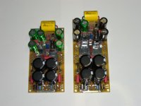
Here's a pic of may latest 60 watt and 100 watt amp prototypes using the same schematic found in post #2, accept I added two more ac filter caps on the boards, and for the 100 watt two more transistors. I'll try to get some measurements out this weekend. If Everything goes well I'll order some boards next week, I figure I should have them two weeks after that. I'm thinking about giving away three pairs for free including shipping with BOM and assembly instructions. I may even include parts, because it's crucial to the performance of this amp. All I ask is that you post your listening impressions on this forum, either this thread or a new one. I prefer someone with a technical background in audio. Some people may think I'm crazy, but I'll love this hobby as much as anybody, and I really want to know what other people think of my work.
Attachments
- Status
- Not open for further replies.
- Home
- Amplifiers
- Solid State
- My Killer Little Amp