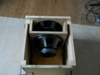
In my interest to continue to learn, I took two Dayton 12" series II drivers and made an isobaric enclosure. I finally put the drivers in this morning and took some measurements. I was hoping for more low end so either the drivers are wrong for subwoofer duty or the enclosure is undersized or ?? Interestingly the measurements do match the included measurements for the driver..... I will include the driver specs PDF and the measurements. I am getting to my questions in the next thread.
Attachments
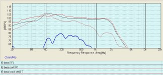
I will include the measurements in this post. I used WinISD to get the enclosure size. The outside dimensions are 16.5"x16.5"x16.5" (or 42cm X 42cm X 42cm). I have three measurements; close mic-ed woofer, close mic-ed vent and then for the heck of it I removed the back and took a third measurement. The last one looks really good. How come the measurement looks good with the back removed? And why do my other two measurements look so different than the WinISD?
Attachments
Hi,
Your box at about 2 cuft is too big for isobaric sealed.
Isobaric vented at around 30Hz tuning should be OK.
Measured nearfield with the back off should give
the same response as the driver on an open baffle.
rgds, sreten.
Your box at about 2 cuft is too big for isobaric sealed.
Isobaric vented at around 30Hz tuning should be OK.
Measured nearfield with the back off should give
the same response as the driver on an open baffle.
rgds, sreten.
A follow up question is why do I have so little output at 50hz but WinISD shows strong output to at least 40hz?
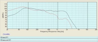
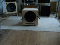
I am using a slot port so I went back and look at my calculation of round port to slot and I was off. I extended the slot port and things look much better. I am considering getting the Yung 300 watt with 6db at 30hz. Can anyone see any issues with getting the 6db boost (I wish it was switchable). Here are latest measurements and some pics.
Attachments
rb132333, have you thought of clam configuration? No need for the chamber, just place the inner woofer from outside, and switch polarity. It may help, but may look ugly though.
HI rb132333,
I think you have done a few mistakes...Looks like there is an Isobaric-chamber Air-leak and as the Drivers have vented Pole pieces, the front Driver will exhibit a Spring Load different from the rear one.
Small but notifiable..But it seems that they are different from each other.
The Port Area Aspect Rate is too high and have a too small Area…
If the Rear leftover Volume is ~45 Liter the tuning should be at ~33 Hz, thus if the Port Area is as is the Length must be larger, (Much larger if picking a proper CSA size=Rec. ~50% larger) than 12.5”. If factoring in the Voice-Coil Inductance:
I.e a Large Voice Coil in Hornresp, the Length needed would be even more and should(IMO) to be partly stuffed with damping Material.
b 🙂
If factoring in the Voice-Coil Inductance:
I.e a Large Voice Coil in Hornresp, the Length needed would be even more and should(IMO) to be partly stuffed with damping Material.
b 🙂
This driver will likely sim fine without the Large Coil tweak, I wouldn't use it. This driver has a somewhat average power handling and rated xmax so this indicates the coil probably isn't large enough to cause serious inductance issues wrt causing an inaccurate sim.
The Dayton 18 inch HO did benefit from the Large Coil tweak though, and it's rated power handling and xmax were pretty normal for an 18 inch driver too, but for this 12 inch driver I'd assume it doesn't need the tweak unless measurements prove otherwise (don't match sims).
Run the simulator but for a single driver and set the VAS for 1/2 of the spec.
This is the best case for an isobaric.
The isobaric MUST have nearly zero leakage, both in the drivers and nil leakage in the enclosure to work best. The smaller the volume of the enclosure between the drivers, the better.
You can experiment with putting the drivers facing each other on the front. They still need to be reasonably well sealed.
Test the seal? Gently press on one, and see that the other moves the same amount, and how long it stays in that position before leaking down. Don't push in a way that offsets the cone and causes the VC to rub - equal pressure.
Now this is a driver with an Fs of about 30Hz. It's not going to work below Fs in any reasonable box. Getting NEAR Fs will require careful tweaking of the box volume, the port and the like. The best you may be able to do is to get some rise in the response before rolloff on the low end.
The Qt of 0.35 is a plus in this instance, since the driver will "try" to work in almost any reasonably sized enclosure, ported or sealed that you pick.
The problem with an amp with a "6dB" boost at 30Hz is what it does below 30Hz. Your driver will run out of excursion FAST unless there is a sharp rolloff below that boost point. Should it keep rising, then the "boost" is essentially useless in practice.
Suggest you run your simulations some more. Set the port for ~35Hz. and see what sort of box volume yields flat or slightly raised output at and above the 35Hz point.
As I said, halve the VAS and compute for a single driver - when actually building DO NOT FORGET to SUBTRACT the volume of the isobaric chamber from the total volume!! Did you do that??
_-_-bear
Last edited:
Thanks for the thought provoking responses. A couple of things; the inner chamber could be smaller. I am confident it is sealed but it could probably be several inches less deep. I will shelve the 6db boost (my original question 🙂 and go with the amp w/o boost. I am not clear on how to size the slot port. I will do some more searches to see if I can find a round to slot converter. Initially the port was 10.5" W x 1.5" H x 6.5" D and I was getting almost no gain. I increased the depth to 12.5" and now I am getting some decent gains. I am not sure how I could make it longer unless I rebuilt the box. This sub may end up getting relegated to my (not built yet) garage. Thanks again!
Hi rb132333,
Here is a quick simulation using the manufacturer's T/S parameters in Hornresp. Hornresp makes isobaric easy: Edit - Tools - Driver Arrangement - Isobaric - pick number of driver and series or parallel; then pick Arrangement, e.g.: Normal Nd.
I'll attach the Hornresp Export and the Input page.
Regards,
P.S.: For port sizing use the port particle velocity as a guide, and keep it below 15m/sec (better: below 10).
Attachments
Last edited:
I am not clear on how to size the slot port. I will do some more searches to see if I can find a round to slot converter. Initially the port was 10.5" W x 1.5" H x 6.5" D and I was getting almost no gain. I increased the depth to 12.5" and now I am getting some decent gains. I am not sure how I could make it longer unless I rebuilt the box. This sub may end up getting relegated to my (not built yet) garage. Thanks again!
Car Audio - PORT Size Calculations and Formulas for WOOFER and Subwoofer BOXES
If you glue 2x 2x2's in your port to take up some of the area, it should be tuned to about the right frequency, assuming rear volume as approx 1.5 cubic feet. Otherwise you can make a 90degree turn and extend the port up the back of the box.
- Status
- Not open for further replies.
- Home
- Loudspeakers
- Subwoofers
- My Isobaric Experiment