Replace the output transformer with a dual voice coil subwoofer with 1Ω coils, you now have a cheap and cheerful subwoofer amp for the car, no inverter, no output transformer required
Remember messin with similar idea a while back.
Never finished working out the bugs and details...
Were twin CCS there to keep the core in balance?
Completely derailed from this train of thought...
Can't remember breakfast, much less what half-
baked nonsense I may have scrambled that day...
I held onto the drawing for some reason...
Attachments
version incomplete
Plz show me , time stamp where you saw this amp , as I look , I can see that your first version resembles mine , however it has a gain of 1 and that is bad , it makes it unstable due to gate capacitance , it will not function as well as mine , secondly it has no zener to antcicipate power line noise . The mosfets are not connected like mine , does that connection work ? I thought the proper connection was source follower ? ...
Thus I dont count this one as nearly similar . show me on diy audio when you posted your design , if before me than I will give you your 10$
I want to see something official.
I have done many different versions of a design like yours here are just a couple that I dugg out of my archive of 1000's of files.
Mostly it was inspired by Susan Parkers design and I have simulated both a transistor drive and an opamp drive system.
Either can be biased in class a or B/AB but biasing class A at such high current can be damaging to the transformer core if something should go wrong on one of the output transistor legs.
I had devised this system last year for use on my ESL's as I use a standard toriod transfomer with a couple of added windings for primary's to drive them.
I have not built it yet but it is on my list of things to try.
The opamp version that I am showing is not my only version but it is one of the first ones I believe I did then I switched to the transistor version.
I can do some more searching of other versions if you wish as I have a lot.
jer
Plz show me , time stamp where you saw this amp , as I look , I can see that your first version resembles mine , however it has a gain of 1 and that is bad , it makes it unstable due to gate capacitance , it will not function as well as mine , secondly it has no zener to antcicipate power line noise . The mosfets are not connected like mine , does that connection work ? I thought the proper connection was source follower ? ...
Thus I dont count this one as nearly similar . show me on diy audio when you posted your design , if before me than I will give you your 10$
I want to see something official.
Last edited:
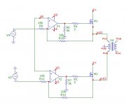
The voltage gain of the opamp version is a little less than 5x (4.77) as it has a an output voltage swing of 43.8V p-p for a 9.18V p-p input.
If you notice it is a current feedback type of configuration and the gain is set by the current going through the FET and the voltage across 1 ohm resistor.
The time stamp on that particular file 2/6/2011 2:56 pm.
And it was drawn from memory on a project I had started in about May and June of last year.
And due to a hard drive crash I may have lost the other versions that I had as I had one that used 2N3055 BJT's for outputs as well.
I have about 11,500 files to search through on just this machine even though many are duplicated many many times over as backups so it is very time consuming to open every file and check it, But one day I will take the time do so and re-organize them.
This crash was mentioned in one of the ESL threads that I was posting in at the time.
The time stamp had also changed to a later date from working on the file at a later date.
The reason I had switch to using transistors is that I was going for a completely class A design and the transistors are cheaper than opamps.
It isn't any thing more than a variation on these circuits of replacing the load resistor or CCS with the transformer.
http://www.diyaudio.com/forums/head...discrete-class-headphone-amp.html#post2596223
This the only the 4th time that I have ever posted any of my circuits as most of them are just designs that I do in Circuitmaker 2000.
I have every intention to give them a try sometime.
But all of the ones I have posted simulate without errors.
The stacked FET versions I have tried and work well using a resistor as the FET load even though the have opamps they are working in full class A mode as the opamp never cross its zero crossing point.
I am not looking for any rewards but you asked and yes I have been working with those and/or that or similar configuration for many years as I had been working with Circuitmaker since it first came out.
And like many looking for the simplest high or medium power amp that can be built using common parts.
I hope that these design are of use to you and help to give you some Ideas as I don't spend a lot of time building amps because I have several large ones that I have been using for quite sometime and suit me well.
However I am interested in ones that can handle peaks of 20khz in to 1 ohm or less becuase of my ESL designs though.
Keep on DIYin' !!!!
jer 🙂
P.S.I don't show any thing in my sims for line regulation because in the real world I always use a regulated supply on the opamps However I do have another High Voltage transistor power amp circuit that runs on a -/+ 500V supply where I did ripple sims ,and did include a feedbaclk circuit to cut the ripple voltage from the output.
Last edited:
LarryB,
I just read your thread and I am not sure what is so special about two inverting op-amps being driven in anti-phase with some arbitrary bias voltage set by a zener diode. Please enlighten me.
I just read your thread and I am not sure what is so special about two inverting op-amps being driven in anti-phase with some arbitrary bias voltage set by a zener diode. Please enlighten me.
LarryB,
I just read your thread and I am not sure what is so special about two inverting op-amps being driven in anti-phase with some arbitrary bias voltage set by a zener diode. Please enlighten me.
That is not the point of this thread .... And what is so special about any amp then ? What exactly do you mean ? I dont need or want special, I want simple and cheap ...
Gerald, those amps are not like mine , mine is used to step up voltage for tesla experiments , its not an audio amp first of all , I have my sennheiser rs 170 for music .
In theory , and in sims , I have already perfected the design for my battery driven 3 phase HV HF sine driver. I have also made a motherboard sized pcb for it ,still never tested it besides testing a single phase " low power with a 30$ transformer , results were very satisfactory .
I need to hand-make myself some transformers.
Last edited:
In my circuit LarryB ,
The current is set by V3 which is set to 4V this sets the current at 4 amps though each FET at 4 amps.
Obviously a single IRF510 can't handle 4 amps at 50v but there are ones that can.
The same goes for any voltage input changes as it directly controls the amount of current through the windings.
jer 🙂
Okay so what voltage are you stepping up to. That would determine the insulation rating. Why do you need three phase, can you not just run a high frequency inverter on single phase. It is a lot easier to make a single phase transformer than a star wound one.
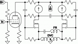
If I am not mistaken here is the circuit drawn properly. All those connections make it look very complex.
yes thx you that is the design , Vb is the zener bias point , I might use your drawing now .
I am not shooting your design down, just checking if there is not an easier solution to the problem.
You may be able to get away with a car ignition coil as it can run at pretty high frequencies and the insulation rating is high.
Feeling inadequate ?
Is Insulting the members the best you can do ? How about spending the time building your "Design" and presenting us with the performance results instead of excuses.
Some Spice scribbles don't count as an effective Design.
82 people read this post and didnt reply , most of them have small wieners and bad haircuts . ( he who replies about this sentence and not about general electronics is as described in this sentence )
Is Insulting the members the best you can do ? How about spending the time building your "Design" and presenting us with the performance results instead of excuses.
Some Spice scribbles don't count as an effective Design.
STALKER ALERT !
The post above should be deleted for being inappropriate .
Hey I am contributing effort to this site , all is free to test and make for all .
Ok I will make a youtube video just for you .
The post above should be deleted for being inappropriate .
Hey I am contributing effort to this site , all is free to test and make for all .
Ok I will make a youtube video just for you .
Last edited:
The difference between the two circuits is that you are putting the transformer load on the source side of the FET and mine is on the drain side.
The reason I did it the way I did is to keep the gate referenced to the ground without any reflected voltages through the transformer effecting the gate voltage.
It just seemed simpler as the way I understand how FET's work.
And that transformers work on the basis of current flow through their windings, I needed to control the current going through them as it was a Class A transformer coupled amplifier for audio.
However I did use the configuration in your circuit in my Variable high voltage supply output stage only I used a transformer to drive them.
I was going to try an opamp driver stage but at the time I was thinking KISS and cheap using junkbox parts and it worked.
I have to admit that I went through a few FET's when the gate voltage either got to high or when the FET's lost its bias reference to ground and stayed on to long for just a split second due to my intermittent solderless breadboard,But that is not a design issue.
jer 🙂
Considering all the feedback, concerns and new drawings... I would have to say you are becoming less and less the inventor of the final amp. How can we say you invented something that does not exist except in concept and is still a changing design based on others' ideas? It seems the amp is born out of progressive ideas with significant problems corrected by other people that change the design, that DIY audio forums invented this amp, someday, when it is finished.
You ask someone to link to the amp. See the link to this topic and others you have posted, fellow DIYAudio members are inventing it along with you. That could make you a project leader if the topics were more diplomatic but...
You ask someone to link to the amp. See the link to this topic and others you have posted, fellow DIYAudio members are inventing it along with you. That could make you a project leader if the topics were more diplomatic but...
Last edited:
ill take that
ok I will accept the idea that the forum invented this amp , and that I was part or it , good enough for me .
ok I will accept the idea that the forum invented this amp , and that I was part or it , good enough for me .
I have not only designed a similar amplifier: a dual Op Amp driving a pair of Push-Pull MosFets, output transformer coupled, but I did it around 1996, commercially producing and selling them in somewhat great numbers (around 100 units).
And even so, I do not claim having had the idea "out of the blue".
I was somewhat inspired by Music Man guitar amps, which uniquely cathode drive 2 or 4 output tubes, with two very high beta power transistors, which in due time are driven by a couple Op Amps.
I thought that a MosFet was, in a way , "the tube and the high beta bipolar all-in-one" equivalent.
Breadboarding proved the validity of the concept.
No Simulation Software way back then, at least none available for me in Argentina.
Some pictures:
1998 Bass Player, happy with his "unplugged" 60W street amp:

2000 Classic Double Bass player , also with 60W Battery Amp.

This is the PCB (2002 upgraded version)
This is the Top Overlay (Parts Layout)
http://img851.imageshack.us/img851/3527/faheymospwroverlay.png
It includes a 555 power oscillator inverter to get the -12V rail (actually 10/11V) for the Op Amp, which is a classic TL072.
The amp includes NFB from the speaker terminals, to provide *some* dmping and lower distortion to a bearable level.
Not Hi Fi by any means, but provided *LOUD* 60W RMS without "exotic" (way back then) converters,
Still a lot of them working , generally at Tourist spots, where AC power is unavailable or impractical (Public Squares, Beaches, Subway Stations, etc.)
jm2c
And even so, I do not claim having had the idea "out of the blue".
I was somewhat inspired by Music Man guitar amps, which uniquely cathode drive 2 or 4 output tubes, with two very high beta power transistors, which in due time are driven by a couple Op Amps.
I thought that a MosFet was, in a way , "the tube and the high beta bipolar all-in-one" equivalent.
Breadboarding proved the validity of the concept.
No Simulation Software way back then, at least none available for me in Argentina.
Some pictures:
1998 Bass Player, happy with his "unplugged" 60W street amp:
2000 Classic Double Bass player , also with 60W Battery Amp.
This is the PCB (2002 upgraded version)
An externally hosted image should be here but it was not working when we last tested it.
This is the Top Overlay (Parts Layout)
http://img851.imageshack.us/img851/3527/faheymospwroverlay.png
It includes a 555 power oscillator inverter to get the -12V rail (actually 10/11V) for the Op Amp, which is a classic TL072.
The amp includes NFB from the speaker terminals, to provide *some* dmping and lower distortion to a bearable level.
Not Hi Fi by any means, but provided *LOUD* 60W RMS without "exotic" (way back then) converters,
Still a lot of them working , generally at Tourist spots, where AC power is unavailable or impractical (Public Squares, Beaches, Subway Stations, etc.)
jm2c
- Status
- Not open for further replies.
- Home
- Amplifiers
- Solid State
- My invention ? Did I invent this amp ?