Nice job.🙂 I appreciate your original approach since it's unique.
I want to ask one question. Why do you use discrete R2R instead of monolithic one like TDA1541 ? If you have many troubles in selecting matched resistors, monolithic is a better solution.
I used to use pcm1704 for several years. After being obsolete, I needed to find an alternative chip or system. Discrete one was out of my sight because of difficulty to have well-matched resistors. Industrial DACs can have 16bit monotonicity ,e.g. ltc2642. I designed my R2R DAC with ltc2642. It was pretty good because I used it for two or three years. It sounded a little bit different from pcm1704 though I intended true copy sound of pcm1704. I still don't know the reason why. LTC2642 was brighter than pcm1704. I preferred a soft pcm1704 tone to ltc2642.
Is your decision based on listening(your ears) or measuring data? LTC2642 has better THD performance than pcm1704 but has a slight glitch. But glitch of ltc2642 is probably the lowest(0.5nVS) in audio application R2R DACs. I would say discrete one has a much large value at least 10 times. My hypothesis is that glitch can change sound color like enhancer in a video system. The more glitch, the more vivid. Some like sharp and clear sound while some like soft and warm one. I prefer the latter.
Hi,
I build this R2R just for fun at first place, and want to learn more about discrete R2R using normal parts and I enjoy tweaking the DAC very much. Of course , I also have a lot of others DAC using others DAC chips. I owned TDA1541 for many years, and also built PCM1704 before. All those monolithic ICs are perform really good. I did measure performance for all my DIY projects for the past few decades, and always end up by fine tune to suit my ears, and I would say, I prefer listening test, and also compare them in front of our local audiophile friends for blind test or passing around among local audiophile friends and ask them to compare and give feedback. From a Japanese audiophile friend , he said there're several similar kits appeared in your country for the past 10+ years? do you have any chance to listen to one yet?
Last edited by a moderator:
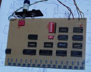
I also experimented with an R-2R discrete DAC, see attachment. It took simultaneous data from an SAA7000 (from a Marantz CD-74), but the project has never been completed. Some ideas might be useful, though. E.g. I provided a calibration facility through an internal word generator for the 8 MSBs and Bourns variable resistors. The declither also has to be worked out yet.
Attachments
I also experimented with an R-2R discrete DAC, see attachment. It took simultaneous data from an SAA7000 (from a Marantz CD-74), but the project has never been completed. Some ideas might be useful, though. E.g. I provided a calibration facility through an internal word generator for the 8 MSBs and Bourns variable resistors. The declither also has to be worked out yet.
Nice. looks like my first version
keep it up and thanks for sharing !
Hi,tru168.
Yes, there are many DIY boards available, which include R2R and DSM, at a reasonable cost in Japan. But I prefer to design myself because I can have a free hand in my PCB, e.g. number of layers, DAC chip, and power configuration. I had been an engineer in a mixed-signal application for 20 years. So, my design tends to use a digital solution based on FPGA. That's why I usually use a monolithic chip though it's possible to employ FPGA which may have better performance than a shift register(74HC595) solution because output driver of FPGA are well-matched and have very low ringing and fast rise and fall time.
My current project is a little bit unfamiliar to DIY since it has a BGA package.
Two way DAC(multibit and DSM)from scratch with input options(SDmicro,toslink and IIS)
If you want to dive into a digital solution, BGA is hard to avoid. I need to populate 8 PCBs to have a real listening test. It's my long and winding road to the door which may lead me to heaven or hell.😉
Hi,tru168.
Yes, there are many DIY boards available, which include R2R and DSM, at a reasonable cost in Japan. But I prefer to design myself because I can have a free hand in my PCB, e.g. number of layers, DAC chip, and power configuration. I had been an engineer in a mixed-signal application for 20 years. So, my design tends to use a digital solution based on FPGA. That's why I usually use a monolithic chip though it's possible to employ FPGA which may have better performance than a shift register(74HC595) solution because output driver of FPGA are well-matched and have very low ringing and fast rise and fall time.
My current project is a little bit unfamiliar to DIY since it has a BGA package.
Two way DAC(multibit and DSM)from scratch with input options(SDmicro,toslink and IIS)
If you want to dive into a digital solution, BGA is hard to avoid. I need to populate 8 PCBs to have a real listening test. It's my long and winding road to the door which may lead me to heaven or hell.😉
Yes, indeed, DIY are more fun. BGA are hard to handle especially for a hobbyist with very limited equipments. Thanks for sharing and I'm reading your post now.
I provided a calibration facility through an internal word generator for the 8 MSBs and Bourns variable resistors. The declither also has to be worked out yet.
It's an interesting project! Internal calibration for R2R is challenging facility. I also designed some ideas at the desk but have never implemented it into a real PCB. I luckily have had another solution to do the same thing. AD9717(high-speed 14bitDAC for RF), which is my current DAC chip for audio application, has an internal calibration system though I don't know the mechanism in detail. It consists of 32banks of 512 resolution DAC. Each 512 resolution DAC has its own calibration register(probably gain control).
You can adjust the register through SPI. Recent high-speed R2R DAC employs such architecture, where distortion mainly depends on the difference between 32 banks because each 512 resolution DAC has little distortion. I guess the calibration register adjust the gain of each bank. If you can find an excellent combination, you have -100dB THD. If you are unsuccessful, you have -80dB THD. This can be regarded as super well-matched registers(0.001%) and normal -matched one(0.01%). I would say -100db THD in R2R DAC is the best score. But I'm not positive it has the difference in SQ. 😉
Hi. No signed magnitude, I had read a lot regarding signed magnitude . I end up with very basic "old school" R2R which is actually convert right justified format, reverse the MSB bit and to transform into COB ( complement offset binary ) . My aim is to make a simple R2R DAC with minimal parts.
I am really confused with this COB business, which has also been mentioned on
http://www.sonicillusions.co.uk/discrete_dac.htm
Please see the Texas Instruments document below:
https://www.ti.com/lit/an/sbaa042a/sbaa042a.pdf
According to these standards, USB - Unipolar Straight Binary coding must be used for a unipolar dac. R2R takes 00...00 and gives 0, and takes 11...11 to give the full scale. To my understanding, BTC - Binary Two's Complement is used for digital audio (page 6). Indeed, if you reverse the MSB of the code given for the BTC Coding Scheme, you simply obtain the code for the USB - Unipolar Straight Binary. What is the deal about COB??
Please illuminate.
As an example, suppose you have eight-bit two's complement code. 00000000 then means 0. Invert the MSB and you end up with 10000000, which is unsigned binary code for 128 instead of 0. That is, there is a big positive offset. Hence, inverting the MSB turns two's complement into offset binary.
Put it through a DAC that expects normal binary code, and you get the desired signal plus a DC offset. An AC coupling capacitor or other type of high-pass can suppress the big offset, leaving only the signal.
Put it through a DAC that expects normal binary code, and you get the desired signal plus a DC offset. An AC coupling capacitor or other type of high-pass can suppress the big offset, leaving only the signal.
Thanks but I need to understand this better. To this end, let me clarify a bit more what I have explained above.
Below is the BTC - Binary Two's Complement code I got from TI document (left column). They represent values from most negative to most positive output potential (Please see the document in the previous post). The column next to it is what we get after reversing MSB. Now, they also go from most negative (just 0 V, this time) to most positive. And, this is what a regular R2R DAC expects to get. Normal binary code.

Hence was the question "where did the COB come from?"
But now I have a second question about your offset. When I compare the above columns, I see that BTC goes from -5V to +5V (lets say) and the MSB reversed case goes from 0 to 10V. This is an offset of some sort, sure, but I don't see what an AC coupling capacitor would take care of in this picture. Am I completely lost?
Below is the BTC - Binary Two's Complement code I got from TI document (left column). They represent values from most negative to most positive output potential (Please see the document in the previous post). The column next to it is what we get after reversing MSB. Now, they also go from most negative (just 0 V, this time) to most positive. And, this is what a regular R2R DAC expects to get. Normal binary code.
Hence was the question "where did the COB come from?"
But now I have a second question about your offset. When I compare the above columns, I see that BTC goes from -5V to +5V (lets say) and the MSB reversed case goes from 0 to 10V. This is an offset of some sort, sure, but I don't see what an AC coupling capacitor would take care of in this picture. Am I completely lost?
As you ask this question on an audio forum, and as audio equipment is not designed to reproduce the bariometric pressure, I assume DC levels are irrelevant for your application. One way to get rid of a DC offset, no matter how large or how small it may be, is an AC coupling capacitor.
If you do care about the DC level, AC coupling won't be acceptable. You will then have to implement some sort of 5 V level shift, or see if the DAC can work with a positive and a negative reference voltage.
Regarding digital formats, a plain old n-bit binary number can only represent integer numbers from 0 up to and including 2n - 1. If you want to represent negative numbers, you have to use some trick, for example two's complement coding or just adding a big offset to shift everything up by 2n - 1, which is known as offset binary coding. As it so happens, the results are the same except for an inverted MSB.
- Home
- Source & Line
- Digital Line Level
- My humble Discrete DAC