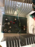
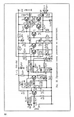
You may have seen my past post about an amplifier based on Germanium devices. Well I've made further progress and modified the initial design which was found in a Russian forum. It was a nice learning experience along the way. I knew how transistors worked but never got into the details of how amplifiers were built around them. Originally the output transistors were soviet but an old Motorola data book led me to a good deal on set of 2N3616. Anyhow here's the original and then my version. Low frequency performance wasn't so great with a 2200uF output cap so it's been upped to 10,000uF. One observation seems to be that older devices tend to have higher distortion figures. Output power is 5-6 watts before clipping. Forgive me for any glaring mistakes 
Attachments
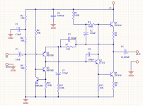

Extremely simple design, I like the CCS loaded voltage amplifier stage. What is the open loop gain? Do you have any measurements, bandwidth and wattage at 1% THD.
How does it sound? (I'm thinking it probably sounds pretty good)
I would love to see some photos. 😀
How does it sound? (I'm thinking it probably sounds pretty good)
I would love to see some photos. 😀
I feel that this subject will force me to go and dig into my stock of germanium 🙄
I understand how that works, fortunately I don't have any germanium transistors. I recently designed a TDA1541A based DAC for a friend, and curiousity has gotten the better of me. I purchased a used TDA1541 from a fellow in Australia a couple of days ago, so I've been sucked in.. LOL I am hoping to better understand all of the hype, the chips are surprisingly expensive. Now to design something - the best part of the project IMO.
Last edited:
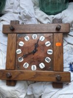
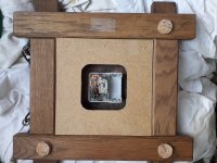
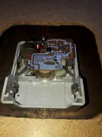
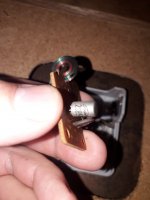
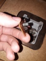
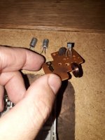
As I have so many germanium trz..today i fixed an old electronic watch 🙂 Tried a low sat silicon trz...but didn't oscillate. Interesting patents from the 50's ...Now looking for a very low leakage pnp germanium trz.I understand how that works, fortunately I don't have any germanium .....I am hoping to better understand all of the hype, the chips are surprisingly expensive
Attachments
-
 20220806_163828.jpg488.1 KB · Views: 141
 -
 20220806_163838.jpg451.1 KB · Views: 139
 -
 20220806_163842.jpg380.8 KB · Views: 120
 -
 20220806_163858.jpg325.1 KB · Views: 142
 -
 20220806_163909.jpg407.2 KB · Views: 138
 -
 20220806_170234.jpg224.4 KB · Views: 133
 -
 20220806_170252.jpg251.8 KB · Views: 133
 -
 20220806_174248.jpg351.4 KB · Views: 148
Now looking for a very low leakage pnp germanium trz.
Good luck on your search as they leak milliamps of current. You could buy a batch and test for leakage. The guitar pedal forums give some good advice on that. I did it for all the small signal transistors so the gains were similar.
Extremely simple design, I like the CCS loaded voltage amplifier stage. What is the open loop gain? Do you have any measurements, bandwidth and wattage at 1% THD.
How does it sound? (I'm thinking it probably sounds pretty good)
I would love to see some photos. 😀
Well there is only one channel on a prototype board on my bench but I'm working on a pcb layout because JLC is so cheap. It's going to be a dual mono design with a capacitance multiplier in the power supply. So each board will be perforated to break the power supply section away. Anyhow here's some quick numbers from my distortion analyzer. It has some linearity issues above 20khz so for the bandwidth test I stopped at 50khz because that is the limit of my Keithley meter. Gain seems to be around 20 as 0.3v input will nearly drive it to nearly full volume.
1Khz into 8 ohms
1w @ 0.094% THD
4w @ 0.38% THD
5.6w @ 1% THD
0.3v input, voltage at 8 ohm load
1khz 5.77v
10khz 5.75v
20khz 5.79v
50khz 4.91v
One thing I don't understand is why on power up the current spikes over 1a for a second or two and then settles down to 800ma.
Attachments
Good numbers particularly given what I suspect is pretty low open loop gain. The closed loop gain should be about 16X based on the schematic feedback components. I'm wondering what the open loop gain is you might have 10 - 20dB of margin?
Is it possible that the inrush current spike is C4 charging current? It's the only possible explanation I can think of off the top of my head.
Is it possible that the inrush current spike is C4 charging current? It's the only possible explanation I can think of off the top of my head.
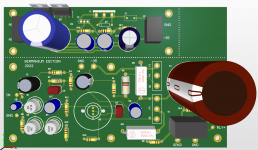
Here's a 3d view of the pcb including the power supply/cap multiplier. The rectifiers are set of common anode/cathode schottky packages and the cap multiplier is Rod Elliot's design. https://sound-au.com/project15.htm
The 1T321 transistor is very similar to size to a TO-5 package and it gets pretty warm so I found some really nice heatsinks on eBay. https://www.ebay.com/itm/274675431820 They do require a bit of filing to fit the soviet package. There's a muting relay on the output because the speaker pop is bad enough.
The 1T321 transistor is very similar to size to a TO-5 package and it gets pretty warm so I found some really nice heatsinks on eBay. https://www.ebay.com/itm/274675431820 They do require a bit of filing to fit the soviet package. There's a muting relay on the output because the speaker pop is bad enough.
Attachments
Howdy, nice looking layout, what copper weight are you planning to use and what is the trace width on the high current paths in your output stage and PSU? Getting as much copper on the board for high current paths is desirable and free since they are removing the copper you aren't using.
I use JLCPCB too, and really like their quick service, reasonable price and the good overall board quality. I've done about 60 PCB designs with them so far.
I use JLCPCB too, and really like their quick service, reasonable price and the good overall board quality. I've done about 60 PCB designs with them so far.
Here's a 3d view of the pcb including the power supply/cap multiplier. The rectifiers are set of common anode/cathode schottky packages and the cap multiplier is Rod Elliot's design. https://sound-au.com/project15.htm
The 1T321 transistor is very similar to size to a TO-5 package and it gets pretty warm so I found some really nice heatsinks on eBay. https://www.ebay.com/itm/274675431820 They do require a bit of filing to fit the soviet package. There's a muting relay on the output because the speaker pop is bad enough.
I think the P217G is almost like a OC35. Someone made this amp:http://livinginthepast-audioweb.co.uk/index.php?p=germanium-amp.
Scroll down for the latest version.
Scroll down for the latest version.
Howdy, nice looking layout, what copper weight are you planning to use and what is the trace width on the high current paths in your output stage and PSU? Getting as much copper on the board for high current paths is desirable and free since they are removing the copper you aren't using.
I use JLCPCB too, and really like their quick service, reasonable price and the good overall board quality. I've done about 60 PCB designs with them so far.
Thanks for the kind words. 1oz copper seems fine and the widths are 0.050" but yeah they could probably be beefed up some. 5 boards at 1oz copper is $10 and going to 2oz brings them up to $30, which is still ridiculously cheap.
@ Astouffer
Do you plan to offer PCBs for sale?
The order will have 3 extra boards so you're welcome to a set. I'll post the gerbers eventually too.
🤗🤗Thanks for the kind words. 1oz copper seems fine and the widths are 0.050" but yeah they could probably be beefed up some. 5 boards at 1oz copper is $10 and going to 2oz brings them up to $30, which is still ridiculously cheap.
The order will have 3 extra boards so you're welcome to a set. I'll post the gerbers eventually too.
I live on the other side of the Atlantic, do you have a problem with that?
- Home
- Amplifiers
- Solid State
- My Germanium based amplifier