I went ahead to do a GainClone Amplifier.
I took the information from this site:
http://diyaudioprojects.com/Chip/Synergy-LM3875-Gainclone/
MY Parts are exactly the same
Differences being, Transformer is an EI core , 24 0 24, 5Amp one
The Bridge was a standard bridge with Caps of value 1pF.
The First Thing I noticed was that one of the diodes were overheating, But the output voltage was in range around 47V between the +V & -V nodes.
Then When I connect the output to a speaker, the voice coil simply burns out.
It seems like the output stage has a large DC current.
Any Ideas if I'm doing anything wrong?
please guide me in the right direction.
Arunkumar14_th said:MY Parts are exactly the same
Differences being, Transformer is an EI core , 24 0 24, 5Amp one
The Bridge was a standard bridge with Caps of value 1pF.
The First Thing I noticed was that one of the diodes were overheating, But the output voltage was in range around 47V between the +V & -V nodes.
Is the diode already overheating, when no speaker is connected? Then there is probably a short to ground on that rail. Or is that diode connected the wrong way round?
47 V is very low. With a nomnal 48 V transformer the no-load voltage should be around 70 V. Is there a short somewhere that makes the voltage break in? What other capacitors do you have in the power supply? Are they all connected the right way round? Do you use a light bulb tester?
Does the IC get hot as well? Then it is probably broken, the reason for the short and needs replacement.
Arunkumar14_th said:It seems like the output stage has a large DC current.
Before you connect a speaker, you should measure the output voltage. If you have DC at the output, you need to find out, where it comes from. Is it from the source? Then use Cin as per National's datasheet or repair or replace the source. Is it from the IC? Then use Ci, if the IC is still okay. If it is not, find out why, repair that and replace the IC.
The best thing is to use either both Ci and Cin or a very good ( = very fast) DC protection circuit.
Arunkumar14_th said:I went ahead to do a GainClone Amplifier.
I took the information from this site:
http://diyaudioprojects.com/Chip/Synergy-LM3875-Gainclone/
MY Parts are exactly the same
Differences being, Transformer is an EI core , 24 0 24, 5Amp one
The Bridge was a standard bridge with Caps of value 1pF.
The First Thing I noticed was that one of the diodes were overheating, But the output voltage was in range around 47V between the +V & -V nodes.
Then When I connect the output to a speaker, the voice coil simply burns out.
It seems like the output stage has a large DC current.
Any Ideas if I'm doing anything wrong?
please guide me in the right direction.
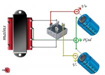
Hi, your V+ to V- should be nearly 70V dc. Your problem could be the 1pF caps? Also check the polarity of the power caps.. The usual mistake is the V- cap, the + side of this cap goes to Gnd. I guess that one rail, V to Gnd, has a different voltage to the other rail..
Basic layout below..
Attachments
Did you test the power supply before connecting the amplifier channels to it? I always test the power supply before hooking up the amplifier to it. Can you unconnect the amplifier channels from your power supply, and test it out.
Have you measured the DC offset of the channels?
Post up some pictures of what you have made.
--
Brian
Have you measured the DC offset of the channels?
Post up some pictures of what you have made.
--
Brian
audio1st, could you explain your picture? My understanding of the Synergy schematic was that the + side of one cap went to pin 1, the - side of the other cap goes to pin 4, and the other pins go to ground.
Hi Arun,
First off, disconnect and check the supply without the amp connected, your voltages should be all correct. As has been said, you should be getting around 35V on each rail or 70V between the rails.
Be sure to not reverse the supplies - this can be catastrophic.
Connect a dummy load to the amp. I use a wirewound 10hm, 50 watt resistor bought from the local market.
Now turn on the supply, and measure the voltage across the resistor, it should not be more than 50mV. Builders here strive for less than 5mV of offset, but even upto 100mV is not catastrophic. Anything more and your amp would be overheating and the resistor may also burn out in the time you take to read this.
Check all your connections again. Note that the input potentiometer also serves as a ground reference, and if you omit you'll have approximately 15VDC on the output, which will burn the speaker coils.
I would advise against building a DC-coupled design like this as a first attempt, try and build it according to the National schema in the datasheet and experiment from there.
Thanks for the reply guys...
My Bridge is not a ready made one as shown in audio1st's post. Instead I built my own bridge with four 3A diodes.
I'll Post the pics of the same by tonight...
I did check the voltages before connecting them to the amp.
The voltages were in the range of 48 Volts DC out on the Bridge rails.
The voltage between ground & V+, ground & V- are the same & is around 24 V even without the amp connected or with the amp connected.
I know it's far less that the specs, but that shouldn't cause the speaker output to have large DC current.
I checked the output Voltage at the speaker terminals..... It shows me a DC voltage of 25V... That's really nasty... & is causing the voice coils to melt away 🙁
I think the Chip is blown up.
It's funny that it happened the same with two chips. Is there any way to verify that the IC is still in good condition?
About the source: The Source cannot have any voltage.. because I'm using a small MP3 player as the source.
Was your input hanging loose or was it tied to ground?
Good advice when you start an amp for the first time:
Check the supply voltage before you'll connect it to the amp
Short the input, measure the DC at the output. Observe or measure the current consumption.
then.... connect a speaker with a small(!) fuse.
then apply music or some test signal.
Are your LM3875 isolated from the heatsink?
I don't understand how you can have a DC voltage of 25V with a supply voltage of 24V - this is not a generator we're dealing with here. There's probably something we're missing.
sorry there sangram... My mistake
What I actually meant was that the voltage was around 25K NOT exactly 25.
Even the input voltages (AC Input 210-230V AC) were varying, as this is not a regulated power supply & it used to change......
Hover over an average of 24
I Took the measurements last night.... and i'm posting this from my memory.... from office....
sorry if i got something wrong.. My bad
NP, as long as the voltage on the output is full positive rail it usually means:
1. DC at input being amplified by the gain factor of the amp. Requires input cap or servo.
OR
2. Absence of Rin which provides opamp with a ground reference.
OR
3. Blown chip.
For those who are confused about the 24V transformer providing 24VDC, this is normal for some Indian manufacturers who don't specify the AC output voltage but the approximate DC voltage after rectification. It's confusing for most, including myself, till I realised what Arun is talking about.
Can you also provide the AC output voltage of the transformer (both loaded and unloaded), so we can verify that the chip is not presenting a dead short to the power supply?
sangram said:1. DC at input being amplified by the gain factor of the amp. Requires input cap or servo.
OR
2. Absence of Rin which provides opamp with a ground reference.
OR
3. Blown chip.
If the output voltage is exactly as high as the rail voltage then the chip is blown. In the other two cases with a working chip the output voltage will be lower than the rail voltage. At least ~0,7 V.
He did say the post was inexact. I suspect that the chip may be blown, but also that since the circuit does not include the capacitor in the feedback loop, there may be some other issues with the implementation which a new chip may not survive.
So lets say the Chips were blown!
It did get overheated!
so lets forget this implementation
Somebody kindly point me the best way to build this amp.
Should I go according to the National Semiconductor datasheet?
also, If I did get this thing working.... In fututre any time, say the chip blows out for reasons unknown.... Wont the speakers connected also go pffffffffffffffffttt???
Is there any mechanism I can prevent this disaster, like a fuse or a Cap on the output stage...
+10 to reading more on Nuuk's site. I read for 6 months before I even attempted a build (DD didn't exist back then, I may have not needed to read as much).
Get the principles correct and yes, the National Datasheet is the best place to start.
Get the principles correct and yes, the National Datasheet is the best place to start.
It won't happen if you do the design work properly. The LM3886 is very relaible you know.Arunkumar14_th said:...If I did get this thing working.... In fututre any time, say the chip blows out for reasons unknown....
Did the LM3886 get cooled by a heatsink? Did you use the LM388TF or LM3886T? If the "T" model, did you insulate properly?
You must try to find out what you did wrong before attempting to use new chips .
If you can't figure that yourself you will need to put up the 'exact' circuit /wiring diagrams of what you did , preferably with pictures.
Without that it would be pretty hard for others to 'see' what is wrong.
But you have several pointers already.... isolated chip from the (earthed!) heat sink ?....etc .
You have another first here......If you are trying a new set up for the first time always try only one channel at a time. You don't want to blow both channels due to some silly error. This is ( probably ) OK if you are using a tried and tested pcb.
Cheers.
- Status
- Not open for further replies.
- Home
- Amplifiers
- Chip Amps
- My GainClone is Blowing up Speakers