I am interested in finding out what changes to the output capacitor would do and Whether I should use the 150ma heater rating or the 6.3v heater rating. Also if anyone has a computer model maybe they can make suggestions for improvement.
I was playing around with the idea of making a tube Headphone Amp. I looked at many designs and decided to make a perfboard prototype instead of using solderless breadboard.
One day I tried using the line out of my dock into a speaker and got very weak sound so I figured maybe the headphone amp would work.
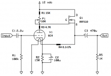
I knocked this together on a 1.75x1.75" perfboard. The two resistors above and below the pot were to make sure I couldn't go to the anode or supply and so I could get more fine adjustment from a single turn pot. The 1/10th ohm resistor is so I could measure the heater current/measure bias(heater voltage).
It seems to work very well. I have been listening to it for a month now although I had to add capacitors to a 12v power supply to reduce noise, I've used it on a 12v SLA battery all day, works great.
The designs I got ideas from are
NP-100v12: DIY 12AU7 (ECC82) Tube / IRF510 MOSFET Headphone Amplifier
DIY 12AU7 Tube Preamplifier Project
Starving Student hybrid
Any suggestion are welcome
I was playing around with the idea of making a tube Headphone Amp. I looked at many designs and decided to make a perfboard prototype instead of using solderless breadboard.
One day I tried using the line out of my dock into a speaker and got very weak sound so I figured maybe the headphone amp would work.
I knocked this together on a 1.75x1.75" perfboard. The two resistors above and below the pot were to make sure I couldn't go to the anode or supply and so I could get more fine adjustment from a single turn pot. The 1/10th ohm resistor is so I could measure the heater current/measure bias(heater voltage).
It seems to work very well. I have been listening to it for a month now although I had to add capacitors to a 12v power supply to reduce noise, I've used it on a 12v SLA battery all day, works great.
The designs I got ideas from are
NP-100v12: DIY 12AU7 (ECC82) Tube / IRF510 MOSFET Headphone Amplifier
DIY 12AU7 Tube Preamplifier Project
Starving Student hybrid
Any suggestion are welcome
Attachments
First put the volume pot on the input. Then get the 6C4 plate voltage up to about 125V. Then we can get to talking on improving the circuit for actual real world use.
Running a 6C4 at such low current and voltage is likely to create quite a lot of distortion, unless signal levels are kept very low. As MrCurwen says, use a lot more voltage. Unless, of course, the aim is simply to have a novelty toy to play with.
I have been driving a speaker (Klipsch 94db) with this for over a month with good fidelity so considering your comments I took some measurements and got 6.37v on filament with 3.1ma plate current. I looked again and found the posted diagram was the original design however I have provided the as built in this Post. I am still interested in the effect that changing the output cap could make.
We are referring to the plate voltage, not the heater voltage. Measured between plate and cathode of tube.
I am certain that the output cap is not the performance bottleneck of this amp at the moment, even though it's probably an electrolytic. Tube amps generally need an output transformer. OTL amps (that have no OT) are probably not the best place to start with tubes.
I am certain that the output cap is not the performance bottleneck of this amp at the moment, even though it's probably an electrolytic. Tube amps generally need an output transformer. OTL amps (that have no OT) are probably not the best place to start with tubes.
I understand about the output transformer design. My mains are pp KT88 monoblocks.
Given that my drive is a function of the load/bias circuit the 6.3v is fixed hence my question about using the 6.3v or the 150ma rating of the heater. I have tried various mfg and found >10% variability in current drawn.
As I said originally I was contemplating this as a headphone amp and took a chance to see what it would do with a high efficiency speaker. I appreciate your information about the capacity of the output as I was wondering how it is calculated.
thx for the feedback
The output cap value can be calculated with standard RC math. There are many handy calculators online, such as RC High-pass Filter Design Tool
Put the load impedance as the R, and the cap value as C. For example with my 120 ohm headphones, your circuit with 470µF cap would give a -3dB point of about 2.8 Hz. A good rule of thumb is to have the -3dB point such that if you multiply it by 10 you get the lowest frequency you want to hear, so 28 Hz in this case.
As per the heater, if I understand you correctly, you are asking is it more important for the heater to be on spec with current, or with voltage. The answer to that is that in reasonable tolerances, it really doesn't matter. I would choose to run the heater at about 6.2 volts to lenghten its life a bit.
For some reason the modified drawing didn't link. Here it is.
I am not sure the wiper is as shown (this is a redraw of original from DIYaudioprojects previously linked) but if it is I will change it to never allow the gate to go to supply rail.
I am not sure the wiper is as shown (this is a redraw of original from DIYaudioprojects previously linked) but if it is I will change it to never allow the gate to go to supply rail.
Attachments

Last edited:
You can't get 3.1mA plate current through 19.7K (minimum) from a 12V supply rail. Either your measurements are wrong or you built a different circuit from the one you showed us in post 1.
Running at a low anode current means that the heater voltage/current is not too critical.
Just seen the new circuit: you can't get 3.1mA through 4.05k from a 12V rail. Anode current is more likely to be around 1-1.5mA.
Running at a low anode current means that the heater voltage/current is not too critical.
Just seen the new circuit: you can't get 3.1mA through 4.05k from a 12V rail. Anode current is more likely to be around 1-1.5mA.
Last edited:
The heater acts as a load for the source follower driving the output. At the same time the heater supply is very clean.
I have been driving a speaker (Klipsch 94db) with this for over a month with good fidelity so considering your comments I took some measurements and got 6.37v on filament with 3.1ma plate current. I looked again and found the posted diagram was the original design however I have provided the as built in this Post. I am still interested in the effect that changing the output cap could make.
I'd make the output cap larger for use with a low impedance speaker, around 1000-2200 uF.
This is a quote from the link to the Millett design.
"In case you're wondering, yes, it's OK to put audio on the tube heaters. Think about it - normally they run on 19V RMS AC. In this case they're running on 19V DC, with a little bit of audio superimposed (rarely more than 1V or so). There could (theoretically) be a little coupling from the filament to the cathode - the cathode resistor is un-bypassed - but it would be negative feedback, and the capacitance from heater to cathode is so low compared to the cathode resistor it would probably only be measurable at RF frequencies."
But that brings up another question, what would unbypassing the cathode resistor do in my circuit?
It would do very little besides lowering gain I'd imagine.But that brings up another question, what would unbypassing the cathode resistor do in my circuit?
Putting the audio signal on the heater means that cathode temperature will vary with the signal envelope. This may have a similar effect to a small bias shift. Probably not worth worrying about in this application, but it does mean that 'heaters affected by signal' cannot always be assumed to be OK.
I might be completely wrong, but my first instict would be that the cathode has such slow thermal properties that it cannot vary so much that it would mean anything. With AC heaters, even if you cut the heater supply, the tube is fully operational for at least a second afterwards.
Anyway, while interesting, this is academic when looking at the schematic as a whole here.
Anyway, while interesting, this is academic when looking at the schematic as a whole here.
It's exactly the same.hence my question about using the 6.3v or the 150ma rating of the heater.
You apply 6.3V, it passes 150 mA .
You apply 150mA , it drops 6.3V
That said, although "it uses a tube" , it's not really "a tube amp" by any means, meaning it does not do , nor have the desirable traits we find in "Tube Amps".
As said before, it's more of a novelty or Science Fair project than anything else.
Nice way to spend a rainy weekend building it, or an exciting project for a beginner, but you already have "real" KT88 powered stuff, don't overthink this project.
It's exactly the same.
You apply 6.3V, it passes 150 mA .
You apply 150mA , it drops 6.3V
That said, although "it uses a tube" , it's not really "a tube amp" by any means, meaning it does not do , nor have the desirable traits we find in "Tube Amps".
As said before, it's more of a novelty or Science Fair project than anything else.
Nice way to spend a rainy weekend building it, or an exciting project for a beginner, but you already have "real" KT88 powered stuff, don't overthink this project.
- Status
- Not open for further replies.
- Home
- Amplifiers
- Tubes / Valves
- My FrankenAmp