Hi,
Are the caps you replaced part of the PS filtering? If so, replacing electrolytic caps with low esr film caps will reducing ripple filtering.
Hence perhaps the increased hum?
Ciao, 😉
Are the caps you replaced part of the PS filtering? If so, replacing electrolytic caps with low esr film caps will reducing ripple filtering.
Hence perhaps the increased hum?
Ciao, 😉
Yes, they are. On B+
Any cure against this reduced ripple? Really wanna keep filmcaps. Sounds darn good!
Any cure against this reduced ripple? Really wanna keep filmcaps. Sounds darn good!
Hi,
You could try to put a 10 to 15R or perhaps higher, resistor between the caps in the B+ rail and see if that reduces the ripple component somewhat.
Also the film caps right after the rectifier should ideally be electrolytics with some esr as well.
Ciao, 😉
You could try to put a 10 to 15R or perhaps higher, resistor between the caps in the B+ rail and see if that reduces the ripple component somewhat.
Also the film caps right after the rectifier should ideally be electrolytics with some esr as well.
Ciao, 😉
You mean between + and - like a bleeder? I have 100k on the last 40uf.
How big can i make the first cap? Smallest electrolytic i have with high voltage is 47uf/400v.
I see many people use filmcaps in their tube gear. Never what problem it could cause.
Do you have any example with this res. In a psu? Interesting to see.
How big can i make the first cap? Smallest electrolytic i have with high voltage is 47uf/400v.
I see many people use filmcaps in their tube gear. Never what problem it could cause.
Do you have any example with this res. In a psu? Interesting to see.
Hi,
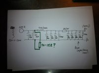
No, not like a bleeder but like the 1K resistor behind choke and first caps.
The 15R resistors can be put between the first and second cap after the choke and so on.
The idea is to smooth the ripple using RC filters up to the 1K resistor.
The P.S. as it is, is not good enough to filter out the ripple hence the hum you're experiencing.
As a general remark, I often see chokes way too big for what they should be doing. If you'd sim such a PSU you'll often find it far less effective than a much smaller choke.
Ciao, 😉
Ok thx for great info.
So are we talking 1 or more, you're saying resistorS. Between each cap ?
I have a bunch of 22ohm kiwame coming in. Would that do?
Have to check tomorrow my stock, if i have something to test with. Maybe some 12ohm there i think.
So are we talking 1 or more, you're saying resistorS. Between each cap ?
I have a bunch of 22ohm kiwame coming in. Would that do?
Have to check tomorrow my stock, if i have something to test with. Maybe some 12ohm there i think.
Hi,
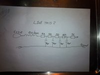
You could start with one resistor between c1 and c2 after the choke and see how that goes.
If it helps you can then add one between c3 and c4 and so on.
You can also try different values starting from say 10R up and so on.
If you can work with a scope or a software simulator then that should speed things up for sure.
If not, trust your ears. After all a permanent truck in the living room can't be too hard to spot, right.😀
I wouldn't waste Kiwame resistors there, any R of sufficient wattage and voltage should do for testing.
Ciao, 😉
Looked at your pic. Yes, that's the idea.
http://www.duncanamps.com/psud2/
Last edited:
Thx🙂
I think i have to trust my ears,
I'll get back tomorrow after some testing.
Yeah the truck gotta go, or else😉
I think i have to trust my ears,
I'll get back tomorrow after some testing.
Yeah the truck gotta go, or else😉
Do you think add more capacitance would also help little or?
After work today i have time to solder in some resistance. Let's see.
After work today i have time to solder in some resistance. Let's see.
Indeed it is!!
So i can also split up my 1K to 4 smaller, like 250ohm between each cap? and skip the 1K totally or?
So i can also split up my 1K to 4 smaller, like 250ohm between each cap? and skip the 1K totally or?
Hi,
Personally I'd put that 47 microF/450VDC cap back in right after the choke, followed by the 1K resistor, then the 10 micro Farad film caps with a low ohm resistor inbetween them.
As I'm working blind I'd advise to take it one step at the time (one channel only is enough for now) and report back.
If the hum source is on the B+ then at some point you'd be able to reduce it to inaudibility, I hope...
Did you measure the heater voltage again?
Ciao, 😉
Do you think add more capacitance would also help little or?
After work today i have time to solder in some resistance. Let's see.
Personally I'd put that 47 microF/450VDC cap back in right after the choke, followed by the 1K resistor, then the 10 micro Farad film caps with a low ohm resistor inbetween them.
As I'm working blind I'd advise to take it one step at the time (one channel only is enough for now) and report back.
If the hum source is on the B+ then at some point you'd be able to reduce it to inaudibility, I hope...
Did you measure the heater voltage again?
Ciao, 😉
It's 6,27V (AC)
Soldering as we speak.. didn't have anything else then a bunch of 22ohm. I'm gonna try with them
Soldering as we speak.. didn't have anything else then a bunch of 22ohm. I'm gonna try with them
It would be best to model your Power supply in PSU2 which is a free download. Its currently seems extremely marginal to me. Just so long as your last cap is a film cap you will get all the benefit that is available from it in terms of tone regardless of the amount of capacitance that comes before it. Pure film cap power supplies are not necessary to achieve excellent results.
Shoog
Shoog
Hi,
Exactly.
Thought you were feeding them from a regulated DC supply?
This is still the SRPP circuit from the pdf file posted on the first pages, is it?
Cheers, 😉
Pure film cap power supplies are not necessary to achieve excellent results.
Exactly.
It's 6,27V (AC)
Thought you were feeding them from a regulated DC supply?
This is still the SRPP circuit from the pdf file posted on the first pages, is it?
Cheers, 😉
I've used Duncans PSU designer earlier in the thread but to be honest. I don't know what to look for. How curves and this should look like to give a good result.
If somebody would give it a try for me i would be happy.
Ok, Shoog. I understand. I can throw in one 47uF.
Where should that be ideal? Right after rectifier? There I have 4,4uF filmcap right now and then comes choke.
Can i put all my filmcaps toghether so the last "pack" is 80uF filmcaps then?
If somebody would give it a try for me i would be happy.
Ok, Shoog. I understand. I can throw in one 47uF.
Where should that be ideal? Right after rectifier? There I have 4,4uF filmcap right now and then comes choke.
Can i put all my filmcaps toghether so the last "pack" is 80uF filmcaps then?
Hi,
Exactly.
Thought you were feeding them from a regulated DC supply?
This is still the SRPP circuit from the pdf file posted on the first pages, is it?
Cheers, 😉
Hehe no, i feed them AC right now with from 6,3V>> 2x330ohm> 330k/100K > ground "voltage divider" it was called i think. That is what i use now.
I got way to low voltage, something like 4,3 up to 4.5V with the voltage reg L7806 i used or came with the kit and the the xformer i have. So that's why AC now. But it worked "ok" up to the point when i start fiddle with filmcaps...😛😀
- Status
- Not open for further replies.
- Home
- Amplifiers
- Tubes / Valves
- My first preamp with tubes