That loop is decorative. AM reception is impossible here with that, but I get 60+ ATSC stations... I also doubt that toroid would effect the AM reception. It's one of the OPTs ") And yes, I've switched off and unplugged all things SMPS in here and tried a traditional tuner with no luck... I mean you can hear the stations, but there is far too much hash. The same happens in my car.
And yes, I've switched off and unplugged all things SMPS in here and tried a traditional tuner with no luck... I mean you can hear the stations, but there is far too much hash. The same happens in my car.
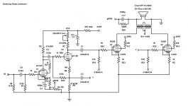
Here's the schematic if anyone is interested.
And yes, I've switched off and unplugged all things SMPS in here and tried a traditional tuner with no luck... I mean you can hear the stations, but there is far too much hash. The same happens in my car.Here's the schematic if anyone is interested.
Attachments
Now i am jealous.... I am building mine for my house but i taking my time because believe it or not i have problems drilling the holes in 3mm aluminum sheet for the tubes. I could just open them but i want to do a clean job so i am waiting for the right screw punch hole opener. Meanwhile i scored a HP339a distortion meter for my personal shack. I also adopted your tone control and i made a nice pcb for it so in the end i will have a nice looking integrated amplifier in a wooden box with aluminum top. I have made some modifications to the original schematic and now it has a feedback scheme like in your schematic with separate 829b biasing circuits and a potentiometer in the Concertina for balancing. Also i now use 6SN7GTs or 6N8S all around because i like the looks of it. May i ask if there is a particular reason for using the 6f12p?
Chris
Chris
Last edited:
I use the 6F12P because I can swing ~140V PP with it, it's simple, and takes less space and heater power than the standard 4 6SN7 Williamson design. As far as chassis holes it's easier for me because the aluminum is 0.050" thick in my chassis. I use a step bit for most holes, and a 1 3/4" carbide hole cutter for the bigger holes.
<1% without gNFB... I know the feeling. I feel weird running American tubes (36LW6) but when they wear out they will be replaced with 6P45S Even my integrated amp only uses 2 pair of USA tubes out of 22 total. 12SN7 (because I had them and it was easier than series wiring for 6N8S) and 12AT7 (because I screwed up during construction and used the wrong plate resistors and again, it was easier, the 12AT7 curves look horrifying! Almost remote cut-off.)
Even my integrated amp only uses 2 pair of USA tubes out of 22 total. 12SN7 (because I had them and it was easier than series wiring for 6N8S) and 12AT7 (because I screwed up during construction and used the wrong plate resistors and again, it was easier, the 12AT7 curves look horrifying! Almost remote cut-off.)I want to be fair so i must admit that all Russian tubes i tried work perfectly including the GU29 although i have plenty of RCA 829B's
I also found that all of ULTRON 6SN7GT tubes i have are actually 6N8P rebranded!
I also want to ask you if those ferrite OTs work better than the iron core ones and how much power you got out with 440V.
Those OTs look pretty compact (small) for the output power 4 829B's can produce.
I now use 700v and 20ma bias current for each valve (40ma per tube) on the output tubes in order to get 70W rms with 0.3% max distortion.
I don't know if i will leave it there, i work the prototype amplifier 8 hours a day 5 days a week in order to see how long it will last and its failure modes if any.
Chris
Last edited:
Those OPTs are power transformers rated at 100VA. I had them... In reality, I should swap them with the 250VA from the 36LW6 triode amp I built. I just reworked it to make 28W of class A power... I haven't measured the power, but PPcalc says 50W in triode, so I'm guessing it's at least that... As far as I know they aren't ferrite, they are "tape measure" cores...
I'm now using 440V, 200V screen, and 70ma cathode current (per tube) and I like it.
I'm now using 440V, 200V screen, and 70ma cathode current (per tube) and I like it.
Last edited:
Thank you for the information!
It might not look like that but i absorb every piece of information i can get, there is no need to reinvent the wheel...
It is strange but once i learn something about electronics i never forget it as opposed to almost everything else.
Chris.
It might not look like that but i absorb every piece of information i can get, there is no need to reinvent the wheel...
It is strange but once i learn something about electronics i never forget it as opposed to almost everything else.
Chris.
You're welcome. I'm basically the same. I'm only 40 but I already walk into a room and forget why.
The story of my life....
Probably stack overflow
Chris
Hi i am on vacations right now, actually i am 6 feet from the sea so it is difficult to send you a diagram. For the power tubes and 600 volts i use 2 of those MINI DC-AC Inverter 12V To 18V220V/380V 500W Boost Step UP Power Module New Hot | eBay one outputs 380v dc after rectification and smoothing and the other 220v for a total of 600v. I added rectification bridges with HE208 diodes and 100 to 470 microfarads smoothing capacitors to each module and then i connected the dc voltages in series. For the preamplifier those are excellent low noise modules DC 12V to 150V-420V DC High Voltage Power PSU Board f Tube amp/ Preamp/ Filament | eBay and DC 12V 24V to DC 100-250V 70W High Voltage Boost Converter Step Up Power Supply 699968764019 | eBay
For biasing i use this 6PC MC34063A Reverse Voltage Module Positive To Negative Voltage Convertor Lot | eBay and +-5V 6V 9V 12V 15V 24V Positive & Negative Dual DC DC Step-up Boost Converter | eBay For the filaments use any step down dc converter but with cooling fins as it will get hot. The result is a light weight, hum free and ultra low noise amplifier with easily filtered dc voltages by using low value and low ESR capacitors. Chris
For biasing i use this 6PC MC34063A Reverse Voltage Module Positive To Negative Voltage Convertor Lot | eBay and +-5V 6V 9V 12V 15V 24V Positive & Negative Dual DC DC Step-up Boost Converter | eBay For the filaments use any step down dc converter but with cooling fins as it will get hot. The result is a light weight, hum free and ultra low noise amplifier with easily filtered dc voltages by using low value and low ESR capacitors. Chris
Attachments

Last edited:
After some testing do not buy this negative dc converter 3PC MC34063A Reverse Voltage Module Positive To Negative Voltage Convertor Lot | eBay
because it gets too hot.
The other one i mentioned is perfect +-5V 6V 9V 12V 15V 24V Positive & Negative Dual DC DC Step-up Boost Converter | eBay
Remember to select the -24v type.
Chris
because it gets too hot.
The other one i mentioned is perfect +-5V 6V 9V 12V 15V 24V Positive & Negative Dual DC DC Step-up Boost Converter | eBay
Remember to select the -24v type.
Chris
- Status
- This old topic is closed. If you want to reopen this topic, contact a moderator using the "Report Post" button.
- Home
- Amplifiers
- Tubes / Valves
- my first post and a question