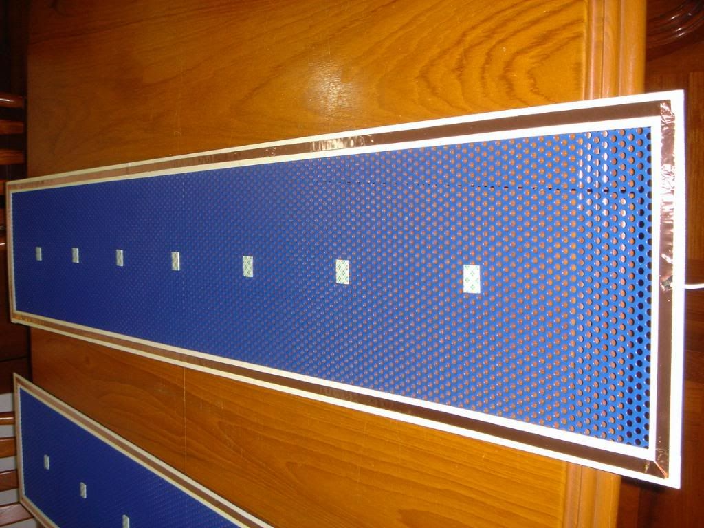
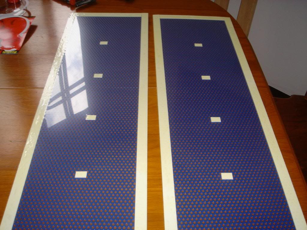
Hello friends! I have learned a great deal about ESL through the making of my headphone. So, I decide to try to make a pair of ESL. The stators are 120x10 cm and 120x25 cm. I use 1 mm spacer for 120x10 cm panels and 1.5 mm for the 120x25 cm panels. The bias voltage now is set up at 1800V for the small ones and 3600 V for the big ones. At the beginning I used a pair of line output transformers for each channel, but I found out that the transformers couldn't take the load and was saturated after around 10 minutes of listening. It was very obvious because the sound was so very distorted. I now use a 8.5K push pull transformer for valve amps for each channel. The coating material I use is the same glue formula I used for my headphone. The sound is really sweet.
I thought that the bass would be bad, but I was wrong. The bass is actually not bad at all. So, I'm going to listen to them without woofer. We'll see how it goes.
Thanks everybody for sharing with me valuable information to help make my ESL a success.
Wachara C.
I thought that the bass would be bad, but I was wrong. The bass is actually not bad at all. So, I'm going to listen to them without woofer. We'll see how it goes.
Thanks everybody for sharing with me valuable information to help make my ESL a success.
Wachara C.
Hi Wachara,
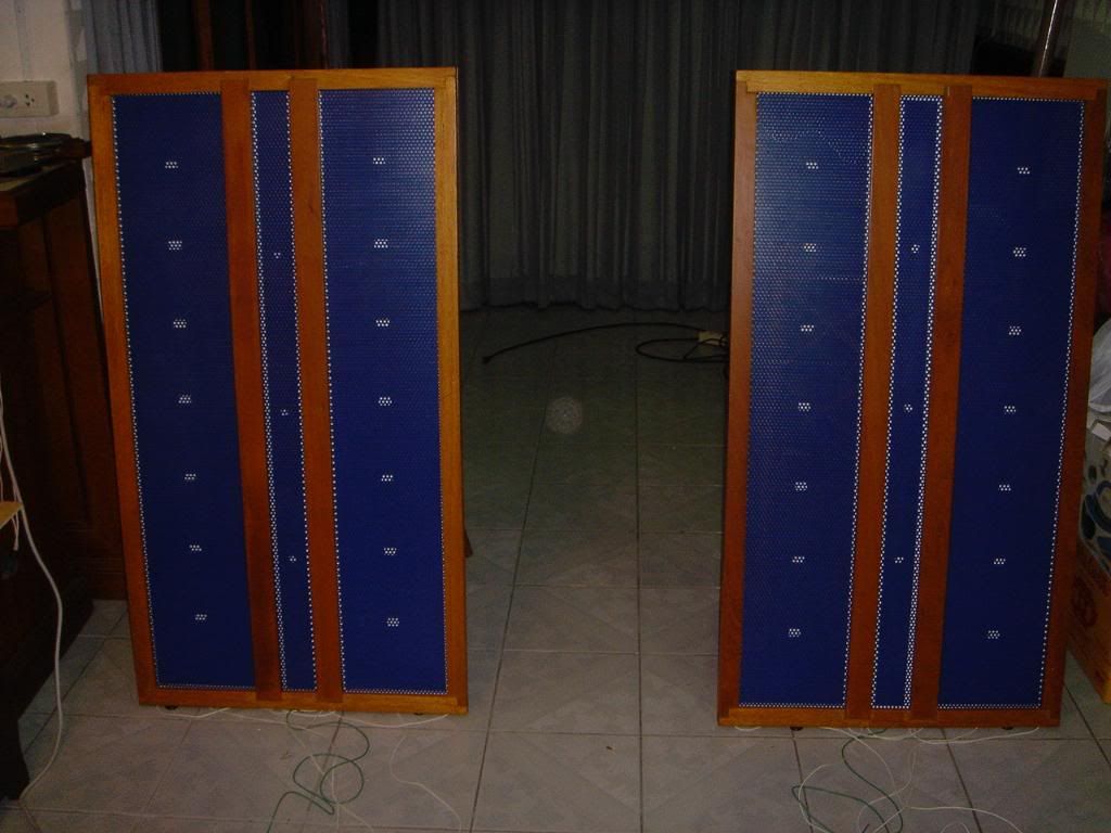
those are two might fine looking ESLs! How do you like the sound? With those two 25cm panels you have quite a lot of surface area which helps with the reproduction of the low end. I suspect they could do pretty nice bass.
Do you have a microphone to make some measurements? You may want to do a basic frequency response measurement to tune the crossover. Do you have the 25cm panels running full range now or do you have them low pass filtered with series resistors?
Hi Arend-Jan,
I like the sound very much. I really like to do the frequencies response measurement, but I don't know how to do it. Could you teach me, please?
I am running them all full range right now. They seem to go together very well. I do not know how to do the low pass filter. Perhaps you can teach me.
I am using only one transformer per channel. Is it still possible to do the low pass filter with one transformer?
I checked with the guy who made the transformer for me and he told me that the step up ratio of the transformer was only 46.5:1. I am wondering if the ratio is too low? I am playing the speakers with my EL34 PP amp. It is rated 25 watts per channel. But when I tried to play the speakers with my Nelson Pass's F5, rated 25 watts per channel, I just could not get the amp to play loud enough. It's weird.
Wachara C.
dont those little pads touching the diaphram keep it from producing sound?
if your building a lowpass filter for woofers you dont tie them into the transformer. They get spliced in before it because the subs most likely cant handle the transformer output.
The simplest low pass filter is as follows...

if your building a lowpass filter for woofers you dont tie them into the transformer. They get spliced in before it because the subs most likely cant handle the transformer output.
The simplest low pass filter is as follows...
Hi Bacon665,
I like to try to put a low pass filter on the big panels. I don't know if I can do it with only one transformer. Thanks for your suggestion though.
Wachara C.
I like to try to put a low pass filter on the big panels. I don't know if I can do it with only one transformer. Thanks for your suggestion though.
Wachara C.
Hi,
a lot of people tend to forget, that the transformers are not only used to step up/down voltages/currents, but to match the impedances. So to know if You´ve got the right transformer it means to measure the impedance of the speakers. 46:1 is a bit low for a panel of this size. But it could be enough if the impedances were alright. In Your case 1.5mm of d/s is a bit high for a hybrid panel and a bit low for a FR-panel. This means a lower capacitance, hence higher resistance of the panel. This in turn means higher transformation factors are needed.
Anyway, the capacitance of the panel as is should be around 900pF, which translates to ~9kOhms@20kHz. This value divided by u² (1/46,5²) gives ~4Ohms. That´s too high. No wonder Your amp doesn´t drive the panels to full volume. While the amp is optimized for low ohmic value loads the ESL presents a too high ohmic value load. regardless of the capabilities of teh amp, power is wasted simply because of the impedance mismatch.
The impedance matching is off of the optimal value. 100:1 would be a better value here. Even better would be a redesign of the panel, since high transformation factors are always sonically inferior to lower transformation factors.
I use between 60:1 and 70:1 (25x125cm) and 50:1 (40x150cm) for the larger panel which is roughly double the size and capacitance. This gives around 1Ohm@20kHz or slightly less. The tranny´s stray inductance goes into resonance with the panel´s capacity somewhere between 12kHz and >20kHz. The resulting peak in the freq-response can be countered by a series damping resistor (typ. 0.5-1.5Ohms) which reduces the low-ohms-stress on the amplifier, linearizes freq-response and allows for a better impedance matching in the lower freq-range.
I wouldn´t use sheet metal stators for a FR-ESL. Wire stators are the better choice when larger d/s values are needed. Sheet metal stators are superior when the d/s is small --> hybrid panels.
So you have two good choices.
a) a hybrid panel made from punched sheet stators, featuring small d/s values and small transformation factors, or
b) a FR-panel made from wire stators, featuring larger d/s values and high transformation factors.
jauu
Calvin
ps. of course You don´t lowpass filter the thingies but high pass them! The series resistance is solely to control the resonance at the upper bandwidth limit.
An easy and very effective way of filtering is to use a dampened C/LR-Filter (2nd order) whith a slightly raised Q value. This way You can counter the phase cancellation around 200Hz, achieve a linear freq-response and highest efficiency....but....it will be a hybrid panel now 😉
chinsettawong said:
I like the sound very much.
And you are running these panels full range? No beaming, huh? And the amps don't mind the capacitance?
Hi Calvin,
Thanks for your input. I really do not understand much about the technical things. I can get only around 50% of what you tried to explain. I'm sorry for my so little knowledge.
Can you suggest to me what I should do? Since I have them done the way they are now. They sound is nice as is now. But if I want to try to produce only lower frequencies in the bigger panels, what do I have to do? To do the R-C filter do I need another transformer?
My EL34 PP amp when playing with these speakers is only at around 40% volume and the sound is loud enough for normal listening. 60% of the volume then the sound is too loud. However, with my F5, turning the volume to almost full still doesn't make the sound as loud as 40% of EL34 PP. I heard from some friends that vacuum tube amps tend to sound louder than the solid state amp at the same wattage. Is it true?
Wachara C.
Hi Analog_sa,
Yes, I run them all full range. I just connect all three big and small panels together to the same transformer. About beaming, it's not that bad. I'm not sure what effect the capacitance can do to the amp. But so far, so good.
Wachara C.
Yes, I run them all full range. I just connect all three big and small panels together to the same transformer. About beaming, it's not that bad. I'm not sure what effect the capacitance can do to the amp. But so far, so good.
Wachara C.
Hi Calvin,
Referring to your post saying that my current speaker Ohm load is too high at 4Ohm. Could you please show me how you calculate that? I put a 1.8 Ohm resister series at the input of the transformer right now. Does that help at all? Also I connect the one 120x10 cm panel and 2 120x25 cm panels to the same transformer. Does that make the Ohm higher?
What do you think about my bias voltage? Now they are 1800V and 3600V.
Wachara C.
Hi Wachara,
Currently you have all panels running full range. Normally for a setup like this you would want only the small middle strip to handle the highest frequencies. Or in other words low pass filter the 25cm panels. You can create a low pass filter very easy by putting a resistors in between the transformer and the 25cm stators. To calculate the frequency you need to know the capacitance of each panel (standard capacitor formula will do) and use the 1/2*pi*R*C formula given by bacon665 in an earlier post to calculate the value of the resistor for a given frequency. The capacitor is the panel itself, the resistor you have to add. You can do this with one transformer.
I strongly recommend you try this as it is likely to improve your speaker in several area's, not the least the high frequency beaming.
If you want I (or someone else) can try to make an estimate for the range of resistor values that you can try. But you probably want to do the frequency response measurements to see what you are doing.
To prevent any confusion, Calvin was talking about crossovers and filters for the case you want to add a subwoofer.
Hi Arend-Jan,
I'm hoping that you can jump in to help me with this issue. I will really appreciate if you can estimate the value of series resisters for me. When we put the resisters, do we put them at the transformer wires that go to the stators?
By the way, how do you measure capacitance of the panel?
Thanks a lot for your help.
Wachara C.
Hi Wachara,
we can calculate the capacitance with the formula
C = E0 * A / d
where
C = capacitance
E0 = 8.85E-12
A = surface area of one plate in square meters
d = distance between the plates in meters
For one panel of 120cm x 25cm this yields 8.85E-10 F, or about 900 pF
Now we apply the forumal F = 1/(2*pi*R*C), or solving for R:
R = 1/(2*pi*f*C).
Let's say we want to low pass filter at 1kHz, then we get R = 180K
You need high voltage resistors, or put multiple (lower value) resistors in series. You could start with 5 resistors of 10K in each wire to the 25 cm stator. This gives a total per panel of 100K.
Hi Arend-Jan,
Thanks so much for your help. It really makes my life a lot easier. 🙂
I will give it a try as soon as I can. And I will report back.
Wachara C.
P.S. How big should the resisters be? Are one watt R OK?
Thanks so much for your help. It really makes my life a lot easier. 🙂
I will give it a try as soon as I can. And I will report back.
Wachara C.
P.S. How big should the resisters be? Are one watt R OK?
You need to measure the draw of the diaphram with max volume (i think) to determine what wattage you need.
To be honest if you were me id be using a 10watt ceramic cased wirewound theyre only like $1.
What i think your looking for with the cross overs is a notch filter (band pass) and a high pass filter.
you can use a low pass on the larger speakers but it will only be cutting off the tweeters range. For the tweeters i can suggest you use a bandpass with the upper frequency limit a couple kilohertz above your hearing range.
Hi,
I overlooked the last picture...so I missed out on the real construction.
Your concept asks for a crossover. This can be done on the primary side of the trannies (because You need a tranny for each channel, bass and treble, or one tranny with tappings) or on the secondary side using just one tranny. In the latter case a simple series resistor forms a lowpass with the bass panels. The wattage can be calculated by I²xR with I the maximum rms current flowing through the resistor and R the ohmic value of the resistor. Since the resistor is connected in series with the panel, the same current I is flowing through resistor and panel. The current value depends on the signal voltage divided by the resistance of the panel (which is frequency dependant and calculates to: R(c)= 1/(2pixfxC)) plus the resistor´s resistance. A capacitor exhibits a falling resistance value with increasing frequency. This means the current rises with increasing frequency. Maximum current occurs at the upper bandwidth limit. The bass panel will be around 900pF. The polarising voltage will be ~2kV-2.5kV (I don´t believe 3.6kV at all with a d/s of 1.5mm 😉 ) If You cross over at lets say 500Hz the panel shows a resistance of 1/(2pix500x900pF) ~ 180kOhms. The maximum signal voltage equals the polarising voltage....say 2.5kV. The maximum current is now 2.5kV/360kOhms=7mA. This is a peak-value, but You need the rms value which is 1/sqr2 of the peak value, hence 7mA/1.4=5mA. The power generated within the resistor is now 5mA²x180kOhms=4.5W. You could use a specialized HV-resistor that is capable of >2.5kV and >5W, or You use a series connection of several resistors with lower ratings.
The middle strip should be highpassed, because if not it will limit the dynamic performance because of its lower d/s. Here You can use a series cap together with a parallel R.
jauu
Calvin
ps. the reason the tube amp is capable of higher volume levels might be, that it isn´t affected as much by a impedance mismatch towards higher impedance values as the transistor amp which is optimized for low impedances. The specified 25W are specified for which impedance? 4 or 8Ohms? A amp specified for 25W@4Ohms would only deliver 12.5W@8Ohms!
Hi Calvin,
Thank you for your kind explanation and guidance. I'll get the resisters and try as soon as possible. 🙂
By the way, about bias voltage, I'm very sure that I bias the bigger panels at around 3,600V. Do you think that it is too high. This might explain why I can use low turn ratio transformers.
Wachara C.
Hi Bacon665,
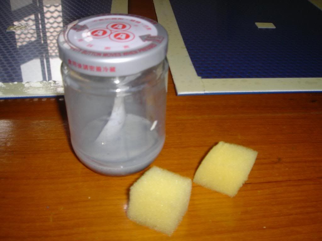
I used double sided tape, therefore I didn't have to wait for the glue to dry.
And since I didn't have the tensioning equipment and I wasn't a perfectionist, I preferred an easiest way to get the job done. I used a hot air gun for final tensioning. 🙂
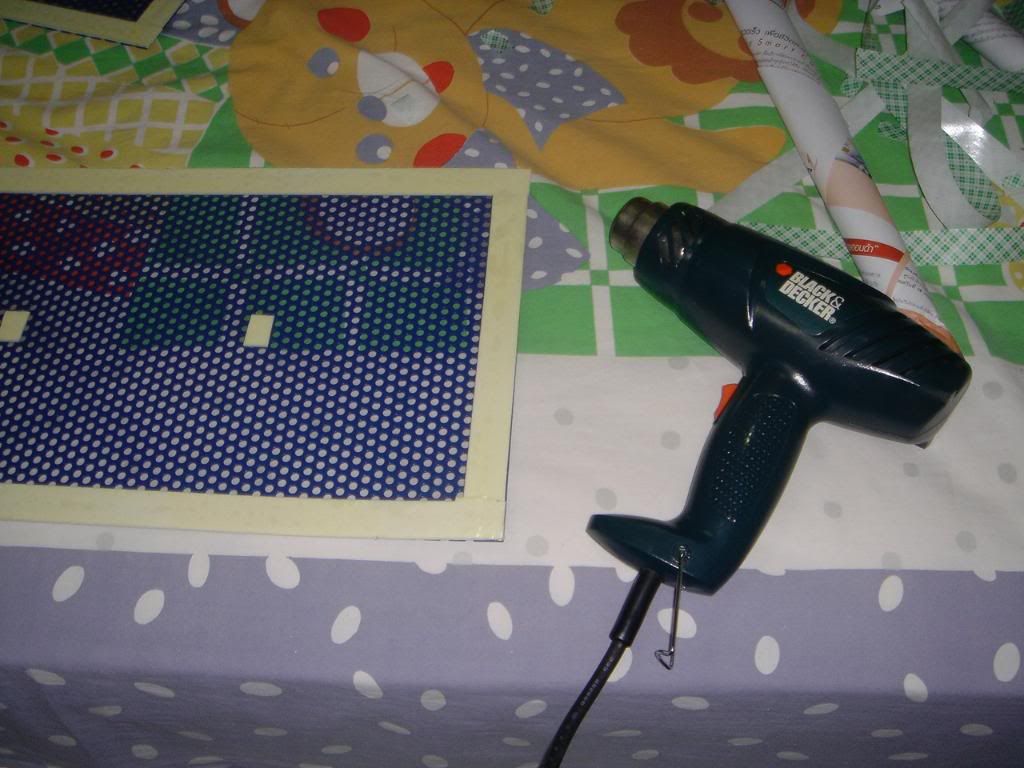
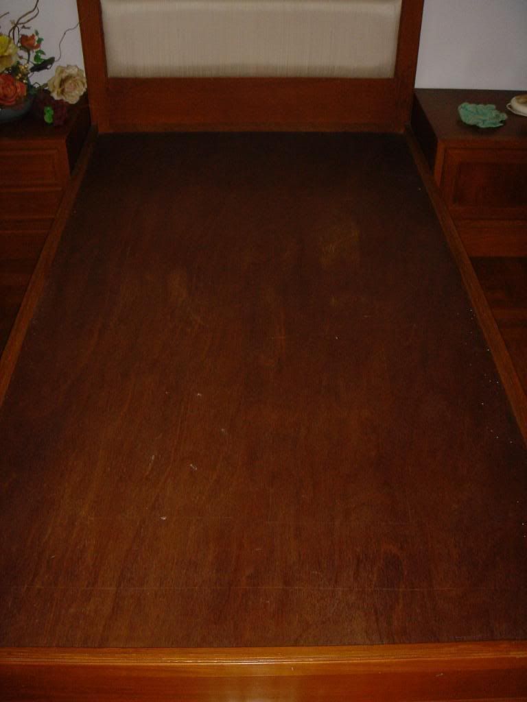
To tell you a secret. When I thought I had to find a big table to put the diaphragm on the stator, I just couldn't find a big enough table for the job. Guess what. I took out my mattress and used my bed as a table. 😀
Wachara C.
I used double sided tape, therefore I didn't have to wait for the glue to dry.
And since I didn't have the tensioning equipment and I wasn't a perfectionist, I preferred an easiest way to get the job done. I used a hot air gun for final tensioning. 🙂
To tell you a secret. When I thought I had to find a big table to put the diaphragm on the stator, I just couldn't find a big enough table for the job. Guess what. I took out my mattress and used my bed as a table. 😀
Wachara C.
- Status
- Not open for further replies.
- Home
- Loudspeakers
- Planars & Exotics
- My first ESL and definitely not my last!