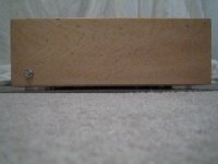
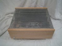
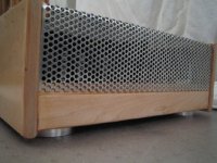
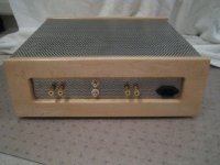
Here are some pictures of my first DIY audio project, the Leach amp.
The hardest part was definately figuring out how to route the chassis wiring, so I got impatient and gave up!
The amp works great, and fired up on the first try. I have the bias current set at 2.0, and a fan to deal with the extra heat. (Theres not much)
With no signal or speaker wires attached, the DC at the output is 5.9, an 6.8 mV for the left and right channels respectively.
(Which I think is good? I matched all the small signal transistors almost exactly)
As this is my first project, I tried to keep it as much a paint by numbers afffair as possible. The circuit boards were ordered from Dr. Leach, and standard issue parts were obtained from digikey, mouser, and a few surplus vendors.
Many thanks to all of the contributers of this forum for continued inspiration for my new addiction!
If anyone has any suggestions for a preamp for which PCB's are readily available, and that would be a good match, I'm all ears.
Attachments
high bias?
is that 2.0mA or 2.0Amps? leach amps are biased at 250mA to make it operate class A at around less than a watt!
anyway, congrats on your new amp.
I have the bias current set at 2.0, and a fan to deal with the extra heat. (Theres not much)
is that 2.0mA or 2.0Amps? leach amps are biased at 250mA to make it operate class A at around less than a watt!
anyway, congrats on your new amp.
Thats interesting, I was unaware of that. Prof. Leach says to set the bias current to 100mA, but I had read in a few places on this forum that raising it to 150mA or 200mA would increase the bass response and improve sound. I didn't compare the two, I just set it at 200mA and started listening. Am I limiting my output in this way?leach amps are biased at 250mA to make it operate class A at around less than a watt!
Attachments

- Status
- Not open for further replies.