Ulas said:But wait, there's more. I found another showstopper. I can already smell the stench of burning ICs. Where there are two there are probably more but why should I waste my time identifying the errors in your design when you reject my suggestions.
Found it! There was a via on the output of U9 that would have shorted the 5V supply to ground. Thanks, Ulas! You made me a wee bit more diligent, at least.
ezkcdude said:So, how do you suggest I learn? Don't I actually have to design and build something first?
I thought the prerequisite to learning was reading, thinking, and studying, not copying. What are you doing at school; reading, thinking, studying, and learning or are you copying? If you pursue a career in research will you do original work based on your knowledge and inspiration or will copy the work of others? Again, those are rhetorical questions. I know what the “correct” answer is and I am pretty sure I know the answer that lies in your heart. Your stated goals for the DAC project were to connect three chips on a PCB and make music. Learning was not one of them. Since you are not interested in learning and just want to make music, why don’t you buy a PCB from Pred? He’s already done a project just like yours except he chose to slave the ASRC.
I’ve already posted my views on series resistors; all you have to do is look for it. What I said about 74AC also applies to 74HC. They were both designed to directly replace the dominant TTL logic families of the day and as such, they are b@stard logic. They source voltage like CMOS and sink current like TTL.
You should know that junior engineers, not chip designers, create evaluation boards and the designs are not definitive. In addition, some engineers use series resisters as a matter of course because that’s the way they were trained or because they are just copying someone else. Whether or not a series resistor is beneficial depends on the nature of the interface, i.e., the characteristics of the input and the output gates. If you don’t know enough to make that determination from the specs then you should include resistor pads for ALL outputs, buy a slew of resistors, try different values and learn first hand.
I’m not going to reply to any more of your posts. You’re like all the others here: You want someone else to tell you what to do and how to do it so you don’t have to read, think, study, or learn.
"................I’m not going to reply to any more of your posts. You’re like all the others here................"
Jeez man , you sound really grumpy . I sincerely hope that whatever is causing such a stressful time will get over soon.
We all want you here and want you smiling when your 'inputs' to the forum will get even better.
Cheers.
🙂
Jeez man , you sound really grumpy . I sincerely hope that whatever is causing such a stressful time will get over soon.
We all want you here and want you smiling when your 'inputs' to the forum will get even better.
Cheers.
🙂
I've been reading more about input transformers for the spdif signal. I'm beginning to think it's a good idea, if it will fit on the board. It seems like a small smt 1:1 trafo would be appropriate here.
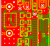
I've added a input transformer for the SPDIF. It's a Schott 1:1 smd (digikey 257-1149-1-ND). I've attached a pic. T1 is the transformer. I have two important questions. First, is this the correct way to connect everything? Second, will this improve the DAC? If so, I will keep the change.
Attachments
I've used the 470-1000-ND from digikey with the CS8416 mux to good effect.
The part you've picked is marked as "Limited quantity available, not recommended for new design."
Either way I think you've wired it wrong.
Keep loops small, ie move G2 near to J1, flip R1 around and connect it directly to C13 etc..
Source termination rarely hurts, if in doubt use something like 15ohms.
Hi EZ!
Ulas is getting angry
In Italy we use to say:"before speaking let count up to ten"!
My suggestion: BEFORE ASKING TRY GOOGLING 😀
Be careful with planes under the input transformers!
Some good info about spdif trafos:
http://www.scientificonversion.com/
(let study the papers!!)
A good one:
Digikey 470-1003-ND
Good readings for the summer:
 http://www.amazon.co.uk/gp/product/0521370957/026-8055571-6499608?v=glance&n=266239
http://www.sigcon.com/bookHSDD.htm
Ulas is getting angry
In Italy we use to say:"before speaking let count up to ten"!
My suggestion: BEFORE ASKING TRY GOOGLING 😀
Be careful with planes under the input transformers!
Some good info about spdif trafos:
http://www.scientificonversion.com/
(let study the papers!!)
A good one:
Digikey 470-1003-ND
Good readings for the summer:
http://www.amazon.co.uk/gp/product/0521370957/026-8055571-6499608?v=glance&n=266239 http://www.sigcon.com/bookHSDD.htmAttachments

mrjam said:Hi EZ!
Good readings for the summer:
Yes. I have read it, though. It doesn't help much with PCB design. I had read that there was a new edition coming out, but I'm not sure if that ever materialized.
Do you think I should cut out the ground plane beneath the trafo?
Hi Evan,
Definitely still interested! Just got back from NY and still playing catchup, but I'll see about getting your BOM ordered next week, if you've still got a spare board.
RandyB
Definitely still interested! Just got back from NY and still playing catchup, but I'll see about getting your BOM ordered next week, if you've still got a spare board.
RandyB
Thanks, Randy! I ordered three boards, and one of them is definitely committed to someone. The other one is a maybe, and the third would probably be mine. So, please don't order anything yet for this project. When the testing is done, I will optimize the design as much as I can (within the limits of the board size, and taking expense of the BOM into account) and then order some more boards, and you would definitely be able to get one. I'll keep updating this thread, and you can always check my project site.

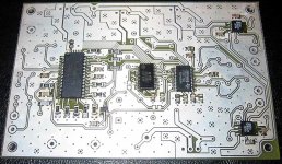
Finally got around to building my DAC. On the plus side, I think I did o.k. for my first surface mount job (so far). Unfortunately, I didn't get to finish because I'm missing a couple of 0805 resistors and had to place another digikey order. I'll finish up everything else when I get those. Anyway, I've attached a pic of the partial build.
Attachments
Ulas said:
What’s the purpose of series resistors on the outputs of the CS8416?
Can you (someone) tell me what is the purpose of these series resistors?
Does the resistors compensate the current flow or what's the purpose?
Google "clock" or "series" + "termination resistor", and you will know about as much as I do. Basically, they are there in case it is important, and if not, they can always be populated with 0 ohm. Had I more time and money I would experiment with different values (100 ohm just seems about right from what I've read, and it's the value given in the data sheets). For now, the board works, so I'm happy.
ezkcdude said:Google "clock" or "series" + "termination resistor", and you will know about as much as I do. Basically, they are there in case it is important, and if not, they can always be populated with 0 ohm. Had I more time and money I would experiment with different values (100 ohm just seems about right from what I've read, and it's the value given in the data sheets). For now, the board works, so I'm happy.
Ok, I find this:
http://www.interfacebus.com/Design_Termination.html
So it's about the trace distance between the receiver and the dac (impedance matching).
I must been sleeping in my RF-course, because these things look familiar now... 😀
macgyver said:
Ok, I find this:
http://www.interfacebus.com/Design_Termination.html
So it's about the trace distance between the receiver and the dac (impedance matching).
I must been sleeping in my RF-course, because these things look familiar now... 😀
Hmm, I can't edit my post...
But in this case these resistors don't stop the reflections (still unmatched impedance), but they reduce the amplitude of oscillations.
- Status
- Not open for further replies.
- Home
- Source & Line
- Digital Source
- My first DAC attempt...PCB help needed