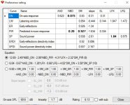
3rd equation exists specifically for use with optimizer,in order to direct the optimizer results
Thus, beyond my capabilities right now.
avoid over-correcting the natural driver rolloff at low frequencies for example.
Thank you! That fixed my Preference Ratings so they are more reasonable now. In my measurements, the woofer SPL increases below 80Hz. When I flattened it I didn't allow it to add boost so I assumed it allowed natural rolloff. But it didn't because my woofer increased in SPL below 80Hz, which caused it to flatten back to 20Hz by pulling the SPLs down. This time I forced it down after 100Hz with a LR8 high pass and it fixed my Preference Ratings. Now I can compare them vs the database measurements at Spinorama dot org to see if I'm heading in the right direction.


the distance from the acoustic reference to the mic must remain constant for all measurements.
I did not keep the distance precise when I moved the microphone to the woofer axis. I kept the reference speaker static so when I moved down to the woofer it would have moved the acoustic reference source a few millimeters closer. I can see why an XLR mic/external sound card setup would be easier and more reliable.
IMO, the directivity mismatch between the horn and the low/mid section is just too great. It's almost like two different speakers spliced together.
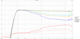
Typical wide radiating bookshelf like Revel:

...and medium-throw PA system:

Successful 8 in+WG designs like JBL 708p or slightly bigger Genelec S360 have wider radiating WGs (+-50..60 deg), and off-axis curves are linear and consistent. No huge 10 dB steps.

I think your WG calls for a bigger woofer or maybe a higher crossover point for less abrupt trasition; maybe the last iteration is smooth enough.
Or you can go all the way and make cardioid mid!
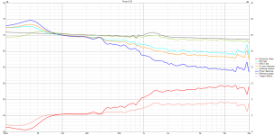
Typical wide radiating bookshelf like Revel:
...and medium-throw PA system:
Successful 8 in+WG designs like JBL 708p or slightly bigger Genelec S360 have wider radiating WGs (+-50..60 deg), and off-axis curves are linear and consistent. No huge 10 dB steps.
I think your WG calls for a bigger woofer or maybe a higher crossover point for less abrupt trasition; maybe the last iteration is smooth enough.
Or you can go all the way and make cardioid mid!
I agree that the directivity mismatch is quite big (I already suggested a cardioid midrange in the other thread). But at the same time I find the DI of the woofer a bit suspicious, I would expect a more gradual rise. But the measurement setup seems very good - strange. Maybe the axis of rotation? I don't know, it just doesn't seem quite right to me.
I'm certain both my measurement and gating are flawed. If something doesn't look right it's something I did.
Member
Joined 2003
I (or we?) can have a look at your .mdats, if you want.I'm certain both my measurement and gating are flawed. If something doesn't look right it's something I did.
I did a quick diffraction modeling in VituixCAD and it seems there is no error in horizontal measurements of your midwoofer section. Ideal 185 mm woofer in a 228x228 baffle recahes +-90 deg beamwidth at 600 Hz, and at 1000 Hz 90 deg FR is down by 9 dB. 800 Hz zigzag is probably reach-around wave inteference.
Thank you. The MDATs are too large to upload to DIYaudio so I created a download link to a Zip file containing the MDATs on Google Drive. Let me know if there is a problem with how I set file access permissions.
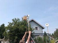
I did not take near field measurements of the woofer and merge them as instructed by VituixCAD. I also used REW's acoustic timing reference but I did NOT make sure the microphone was equidistant to the acoustic reference source when I lowered the microphone from the tweeter axis to the woofer axis. So don't waste a lot of time trying to make anything correct. Mostly, just use the data to see what happens when someone uses REW's acoustic reference without doing it exactly right. I need to purchase an XLR mic + external soundcard so I can take better measurements in the future. The speaker was elevated 10 feet (3.048 meters) then rotated 0 to 180 degrees at 5 degree increments. Microphone was 80 inches (2032 mm) from the drivers.

I did not take near field measurements of the woofer and merge them as instructed by VituixCAD. I also used REW's acoustic timing reference but I did NOT make sure the microphone was equidistant to the acoustic reference source when I lowered the microphone from the tweeter axis to the woofer axis. So don't waste a lot of time trying to make anything correct. Mostly, just use the data to see what happens when someone uses REW's acoustic reference without doing it exactly right. I need to purchase an XLR mic + external soundcard so I can take better measurements in the future. The speaker was elevated 10 feet (3.048 meters) then rotated 0 to 180 degrees at 5 degree increments. Microphone was 80 inches (2032 mm) from the drivers.

Last edited:
I've finally had a look at .mdats.
Your measurements and setup, barring timing reference validity question, are near flawless. Here are my suggestions to make them slightly more precise a lot less labor intensive:
1)rotational axis should pass through acoustic center, not some arbitrary point like waveguide edge. The deeper the device (deep cone, large waveguide), the greater the error will be. For a (kinda crappy) 13 cm deep horn the difference in PIR, LW, acoustic power is 2 to 3 dB.

Or, in raw form:


2)For a modular speaker like yours measuring whole thing at once is more difficult and somewhat counterproductive. Woofer barely "see" WG if at all; for waveguide, reflections from the box cannot be compensated in crossover and only add noise to the measurement. For a whole system, WG to midwoofer distance is not a fixed variable, so nothing is gained from measuring assebled speaker, unlike traditional one box, one baffle designs. I would measure such a system like this:
-ground plane measurements for woofer box, uncompensated (as it will always sit on the floor, I presume, and get 2pi reinforcement). Optionally, do a vertical measurements with the box still on the ground and mike changing position for additonal precision; but it's cumbesome and almost no-one, barring Keele in his CBT paper, does it.

-on-pole measurement for a horn, like you did
As both devices are axisymmetrical, single-orbit (hor) measurements will be sufficient. 5 deg step is excessive, no precision would be lost by switching to 10. Overall, this would reduce your workload from 148 measurements to 36, and will allow for more flexibility in VituixCAD (ability to freely change vertical distance between sources).
3)As for gating, you have 3 distinct reflections at 12, 45-47 and 65 ms. For horn it makes no advantage to gate after 12 ms, for woofer all point have some value: 12 ms gives the most valid HF response, 45 would shove midrange resonances (not much use for closed box, but helpful for troubleshooting vented or cardioid boxes), 65 shows true LF extension. For export to VituixCAD I would gate at 12 or 45 ms.


Also, gating cuts off wind/traffic noise. Notice how the very same measuremt shows bass extension almost to DC if I gate it at 1000 ms:

4)For the wind noise I would buy or make open cell foam spherical windshield likke this:

5)For HF measurements 25-30 cm turntable is a significant reflective surface. If I am not wrong, it pollutes DE11 dataset with a somewhat strong reflection at 5 ms resullting in +-0,5 dB ripple. Covering it with some 15-20 cm tall fiberglass or foam wedges would clean impulse response and allow for more in-depth analysis of waweguide behaviour.


Or maybe use smaller fixture, though it's a more expensive solution, and, while it will hold the weight of almost any horn, I'm not sure it would suffice for heavy cabinets.

(just for reference)
Don't take the above as strong criticism; your measurements are amongst the best I've seen from a non-anechoic environment, and, with small adjustments, can be made near perfect.
Your measurements and setup, barring timing reference validity question, are near flawless. Here are my suggestions to make them slightly more precise a lot less labor intensive:
1)rotational axis should pass through acoustic center, not some arbitrary point like waveguide edge. The deeper the device (deep cone, large waveguide), the greater the error will be. For a (kinda crappy) 13 cm deep horn the difference in PIR, LW, acoustic power is 2 to 3 dB.
Or, in raw form:
2)For a modular speaker like yours measuring whole thing at once is more difficult and somewhat counterproductive. Woofer barely "see" WG if at all; for waveguide, reflections from the box cannot be compensated in crossover and only add noise to the measurement. For a whole system, WG to midwoofer distance is not a fixed variable, so nothing is gained from measuring assebled speaker, unlike traditional one box, one baffle designs. I would measure such a system like this:
-ground plane measurements for woofer box, uncompensated (as it will always sit on the floor, I presume, and get 2pi reinforcement). Optionally, do a vertical measurements with the box still on the ground and mike changing position for additonal precision; but it's cumbesome and almost no-one, barring Keele in his CBT paper, does it.
-on-pole measurement for a horn, like you did
As both devices are axisymmetrical, single-orbit (hor) measurements will be sufficient. 5 deg step is excessive, no precision would be lost by switching to 10. Overall, this would reduce your workload from 148 measurements to 36, and will allow for more flexibility in VituixCAD (ability to freely change vertical distance between sources).
3)As for gating, you have 3 distinct reflections at 12, 45-47 and 65 ms. For horn it makes no advantage to gate after 12 ms, for woofer all point have some value: 12 ms gives the most valid HF response, 45 would shove midrange resonances (not much use for closed box, but helpful for troubleshooting vented or cardioid boxes), 65 shows true LF extension. For export to VituixCAD I would gate at 12 or 45 ms.
Also, gating cuts off wind/traffic noise. Notice how the very same measuremt shows bass extension almost to DC if I gate it at 1000 ms:
4)For the wind noise I would buy or make open cell foam spherical windshield likke this:
5)For HF measurements 25-30 cm turntable is a significant reflective surface. If I am not wrong, it pollutes DE11 dataset with a somewhat strong reflection at 5 ms resullting in +-0,5 dB ripple. Covering it with some 15-20 cm tall fiberglass or foam wedges would clean impulse response and allow for more in-depth analysis of waweguide behaviour.
Or maybe use smaller fixture, though it's a more expensive solution, and, while it will hold the weight of almost any horn, I'm not sure it would suffice for heavy cabinets.
(just for reference)
Don't take the above as strong criticism; your measurements are amongst the best I've seen from a non-anechoic environment, and, with small adjustments, can be made near perfect.
For Vituix the Rotation point should be the centre front of the baffle or equivalent. Measuring from the acoustic centre is perfectly valid with other tools.1)rotational axis should pass through acoustic center, not some arbitrary point like waveguide edge.
Graphic representation in the instructions
https://kimmosaunisto.net/Software/VituixCAD/VituixCAD_Measurement_REW.pdf
There is a slight loss of precision as there is more interpolation in the software, but for most cases it is likely not worth the extra effort if a manual table is being used.5 deg step is excessive, no precision would be lost by switching to 10.
IME, "benign" or "simple" sources like low-diffraction horns or pistonic drivers on optimised baffles gain very little from increased angular resolution, as responses in the frontal hemisphere are near copies of each other.There is a slight loss of precision as there is more interpolation in the software, but for most cases it is likely not worth the extra effort if a manual table is being used.
There are some anomalies in the back, where several secondary sources - edge diffraction, diffraction on driver itself - can interact unpredictably, but their weight in DI/PIR/SP is low, and such anomalies are typically narrowband, like this 5.9 kHz hole, which is present in 130 degree curve, but not in 125 or 135.
With complex sources like resistive cardioids there can be more such anomalies in frontal hemisphere which has more weight perceptually, so measuring them at 5 degree increments can be worthwhile.
Actually, no, see further in the manual:For Vituix the Rotation point should be the centre front of the baffle or equivalent.
Non-shallow waveguide is similar to the stepped baffle from the measurement point of view.Rotation center on Z-axis varies with stepped baffle. Drivers on each baffle level has own rotation center on Z-axis. Distance from each baffle level to microphone should be the same (1000 mm). Differences on Z-axis are entered to the simulator as Z mm of driver instance in XO. For example, tweeter Z=0 mm, mid-range Z=-20 mm, woofer Z=-100 mm.
Somewhat OT, but CEA2034 have similar misconception. It prescribes to have axis of rotation no more than 50 mm behind the baffle, so spinorama somewhat misrepresents horn speakers.
BTW, here's something you can instantly compare with:
https://www.audiosciencereview.com/forum/index.php?threads/neumann-kh120-ii-monitor-review.46362/
(You're already better 🙂)
https://www.audiosciencereview.com/forum/index.php?threads/neumann-kh120-ii-monitor-review.46362/
(You're already better 🙂)
@VoxCelestial
Thank you for your detailed explanation. That's a significant help. I didn't know how to measure the freestanding horn. You made it clear now. You also explained how I should measure if I convert the woofer enclosure to cardioid which was one of the recommendations earlier in the thread. Again, thank you for explaining how to improve the measurements.
Thank you for your detailed explanation. That's a significant help. I didn't know how to measure the freestanding horn. You made it clear now. You also explained how I should measure if I convert the woofer enclosure to cardioid which was one of the recommendations earlier in the thread. Again, thank you for explaining how to improve the measurements.
There is discussion of this topic hereActually, no, see further in the manual:
https://www.diyaudio.com/community/threads/vituixcad.307910/post-7391829
- Home
- Loudspeakers
- Multi-Way
- My First Crossover, 2-Way w/ VituixCAD
