Hi!
I have designed my first class D output stage now and wounder if anyone could give me some positive/negative feedback.
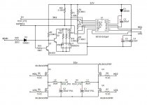
The schematic consists of the output stage with FETs and LC output filter. The switch frequency will be around 50kHz or a bit higher and the amp will be for subwoofer use.
The gate driver is from IRF and is the one i thinks suits this full bridge project well. It has a built in dead time generator and OC function. The OC signal will in my design automatically shut down the driver, is this a good way to do it?
The design is made so the dead time can be adjusted via J1.
The shdn input may be a bit crazy haven't thought that through yet, what do you think?
Would Coilcraft DMT3-35-12L coil be good in the output filter?
Hoping for some tips and tricks =)
I have designed my first class D output stage now and wounder if anyone could give me some positive/negative feedback.
The schematic consists of the output stage with FETs and LC output filter. The switch frequency will be around 50kHz or a bit higher and the amp will be for subwoofer use.
The gate driver is from IRF and is the one i thinks suits this full bridge project well. It has a built in dead time generator and OC function. The OC signal will in my design automatically shut down the driver, is this a good way to do it?
The design is made so the dead time can be adjusted via J1.
The shdn input may be a bit crazy haven't thought that through yet, what do you think?
Would Coilcraft DMT3-35-12L coil be good in the output filter?
Hoping for some tips and tricks =)
Attachments
I just noticed two errors in the schematic i uploaded.
R19 is not really needed and J1 should of course be connected to GND.
R19 is not really needed and J1 should of course be connected to GND.
Hi smitten,
another error in your schematics...
your must use 2 fets drivers to drive your output bridge
feeded by pwm signal with phase shift of 180° or same pwm signal for both drivers but outputs inverted compared to the other driver...
another error in your schematics...
your must use 2 fets drivers to drive your output bridge
feeded by pwm signal with phase shift of 180° or same pwm signal for both drivers but outputs inverted compared to the other driver...
Thanks for the response alexclaire. I do use two drivers but in the schematic I posted I only had one of them.
I know my first schematic probably was so bad that no one understood it. I have a new version now that will be used to make the first prototype.
If anyone has any comments on the new schematic I would appreciate it.
I have some trouble finding good parts for the output filter. I have found a nice torroid from Coilcraft but I have not found a suitable cap yet.
The f-3dB frequency must be rather low since I use 50kHz fswitch. I could also try to find a bigger coil than the 35uH from Coilcraft and then get away with smaller cap.
Any ideas?
Hoping for more response this time 😀
Attachments
Hi,
T106-2 core are very good for class d amplifier output filter...
polarized caps are not good for output filter !!!
cap range is 100nF---->4,7uF depending on f-3db
f-3dB should be 5kHz or less for your application.
T106-2 core are very good for class d amplifier output filter...
polarized caps are not good for output filter !!!
cap range is 100nF---->4,7uF depending on f-3db
f-3dB should be 5kHz or less for your application.
Hi again, sorry for my late response.
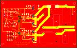
I have done some changes in the schematic and also made a PCB. Tell me if you thiink it looks ok. I will probably also do a PWM modulator stage with subsonic filter and more but that will be on a separate board. This is because the output stage is mainly going to be drived by a DSP.
I choose a big 22uF polyester cap and a coilcraft 77uH coil for the filter, should work.
I do not have any feedback in this configuration but I am thinking of puting in some test points where feedback could be fed to the modulator board I am currently designing.
I really need some more information on feedback topologies. I guess the most common is to take feedback pre filter and LP filter it with perhaps a fourth order filter and the compare it to the input signal? Maybe even trying post filter feedback and LP filter the feedback signal again to remove almost all switch frequency components so the system should be stable? Any ideas on this?
I do not think I will need the fly wheel diodes since the diodes in the MOSFETs are quite fast. But I have made it possibel to mount them if necessary.
PCB
Schematic

I have done some changes in the schematic and also made a PCB. Tell me if you thiink it looks ok. I will probably also do a PWM modulator stage with subsonic filter and more but that will be on a separate board. This is because the output stage is mainly going to be drived by a DSP.
I choose a big 22uF polyester cap and a coilcraft 77uH coil for the filter, should work.
I do not have any feedback in this configuration but I am thinking of puting in some test points where feedback could be fed to the modulator board I am currently designing.
I really need some more information on feedback topologies. I guess the most common is to take feedback pre filter and LP filter it with perhaps a fourth order filter and the compare it to the input signal? Maybe even trying post filter feedback and LP filter the feedback signal again to remove almost all switch frequency components so the system should be stable? Any ideas on this?
I do not think I will need the fly wheel diodes since the diodes in the MOSFETs are quite fast. But I have made it possibel to mount them if necessary.
PCB

Schematic

- Status
- Not open for further replies.
- Home
- Amplifiers
- Class D
- My first class D output stage feedback wanted!