
meanman1964 said:Nelson,
What do you think could be the problem?
Transformer proximity and grounding. You'll have to play with
it to see what makes it better.
It's a Zen RevisitedGRollins said:Perhaps I missed a post somewhere...exactly which class A amp is this?
Grey
Maybe a silly question but can I connect the + speakerterminal and input grounding direct onto the rectifier negetive pole?
Another silly question,what about the grounding and earthgrounding do I connect them together and what's the way to do it?
Another silly question,what about the grounding and earthgrounding do I connect them together and what's the way to do it?
I am asking my self
why everybody building pass amps
without chokes in PS,
and with no separate PS...
why everybody building pass amps
without chokes in PS,
and with no separate PS...
meanman1964 said:Maybe a silly question but can I connect the + speakerterminal and input grounding direct onto the rectifier negetive pole?
Another silly question,what about the grounding and earthgrounding do I connect them together and what's the way to do it?
Dont connect anything else to the rectifiers than the trafo and the PSU-caps! A good starground point is between the last two caps in the PSU.
Since its a Zen Revisited, how does you PSU arrangement look like?
Did you make the CLC supply as per the article? Its a bit hard to tell from the pic's.
🙂
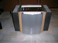
Hi! Nice amp you built there. The chassis looks like a lot of work went into this amp. So let's make sure it also sounds that way.
The first thing to do is to make twisted pairs out of all the wires which carry AC, which means
twist the wires from the switch going to the transformer
twist the wires from the transformer going to the rectifiers
twist the wires from the rectifiers going to the boards
twist the wires from the boards to the outputs
and so on. This prevents wires from picking up any noise (from the transformer for example) and looks neat.
Also make sure that the amp and the preamp and the sources are plugged into “the same circuit”. By that I mean that you should use wall-outlets from the same circuit to avoid ground-loops. In one corner of my living room there's a “bad” outlet. Any source powered by this outlet causes huge amounts of hum in my system. Ground-loops, man, avoid them.
Now, two questions:
When you say hum, you mean hum coming from the loudspeakers (both channels?) or hum coming from inside the amplifier? Let's assume you mean hum from the loudspeakers.
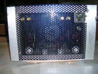
What's that board in the middle? Slow-start?
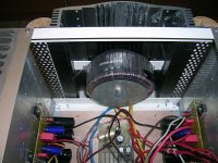
Let's see, looking at the attachments, I assume the following:
You use one toroid transformer for both channels, so there are two possibilities:
a) your transformer has one secondary winding which you use for both channels
b) your transformer has two separate secondary winding, one for each channel
Please let us know which configuration you are using. (b?)
Okay, then I see two bridge rectifiers. And on each board I see two large electrolytics, then something I suspect being an iron-core inductor and another two electrolytics. Right?
Looks just like the CLC-supply Mr. Pass suggests in his Return of Zen-Paper.
The iron core inductors could be a problem. If the circuit draws too much current, the core will saturate and the inductor will let the ripples pass unfiltered. This will result in a 100Hz hum (50Hz rectified is double the frequency) appearing at the output.
Solution: Replace the iron-core inductors with big, bulky air-core inductors. You can use the ones used in crossovers or even a spool of wire. I'm using 0.5kg of 1.25mm wire per channel in my Zen lite. Just make sure the inductor can handle the current.
Grounding and earth-grounding:
To me it looks like this: You are using circuit boards, and I can see that the output's ground is terminated there. And it seems like you use some shielded cables from the inputs to the board. So the psu's ground, the input's ground and the output's ground are all terminated at the circuit boards, right?
So basically, the input's ground, the output's ground and the circuit's ground should meet at the first capacitor (the first from the rectifier that is). This point shall be called ground-point. By now each channel has it's own ground-point. Now you need to earth-ground things.
The chassis should be directly earth-grounded. Make sure that all the metal parts of the chassis are connected to each other and make an earth-connection with a nut and a bolt somewhere. Thats your earth-ground-point.
The way you connect the ground-points with that earth-ground-point somewhat depends on personal taste. What I wouldn't do is to just connect them with a piece of wire. Why? Ground-loops, man. No, seriously, consider the following: Your preamp is earth-grounded, directly. Now you connect it to your amp (which is directly earth-grounded as well) via interconnects. Then you plug both of them them into a multi-outlet power strip. Now there is a connection outlet-powercord-preamp-interconnect-amp-powercord-otlet. This basically is one big loop of wire. And electromagnetic fields will happily induce noise, hum and the like.
Solution: In his Firstwatt amplifiers Mr. Pass is using CL60-type thermistors. Some people are using anti-parallel diodes or small value high power resistors. I myself use a 10R 3W resistor in my preamp and anti-parallel diodes in my amp. The thermistor /resistor/diodes acts an a loop-breaker. But if something happens, like a wire coming loose and touching the chassis, the thermistor/resistor/diodes will conduct and maintain safety.
The thermistor is probably the most stylish option.
Now there are two possibilities.
a) one secondary
Connect each ground-point with one leg of the thermistor. Connect the other leg of the thermistor to ther earth-ground-point.
b) two secondaries
Connect each ground-point to the earth-ground-point through a separate thermistor.
The first thing to do is to make twisted pairs out of all the wires which carry AC, which means
twist the wires from the switch going to the transformer
twist the wires from the transformer going to the rectifiers
twist the wires from the rectifiers going to the boards
twist the wires from the boards to the outputs
and so on. This prevents wires from picking up any noise (from the transformer for example) and looks neat.
Also make sure that the amp and the preamp and the sources are plugged into “the same circuit”. By that I mean that you should use wall-outlets from the same circuit to avoid ground-loops. In one corner of my living room there's a “bad” outlet. Any source powered by this outlet causes huge amounts of hum in my system. Ground-loops, man, avoid them.
Now, two questions:
When you say hum, you mean hum coming from the loudspeakers (both channels?) or hum coming from inside the amplifier? Let's assume you mean hum from the loudspeakers.
What's that board in the middle? Slow-start?
Let's see, looking at the attachments, I assume the following:
You use one toroid transformer for both channels, so there are two possibilities:
a) your transformer has one secondary winding which you use for both channels
b) your transformer has two separate secondary winding, one for each channel
Please let us know which configuration you are using. (b?)
Okay, then I see two bridge rectifiers. And on each board I see two large electrolytics, then something I suspect being an iron-core inductor and another two electrolytics. Right?
Looks just like the CLC-supply Mr. Pass suggests in his Return of Zen-Paper.
The iron core inductors could be a problem. If the circuit draws too much current, the core will saturate and the inductor will let the ripples pass unfiltered. This will result in a 100Hz hum (50Hz rectified is double the frequency) appearing at the output.
Solution: Replace the iron-core inductors with big, bulky air-core inductors. You can use the ones used in crossovers or even a spool of wire. I'm using 0.5kg of 1.25mm wire per channel in my Zen lite. Just make sure the inductor can handle the current.
Grounding and earth-grounding:
To me it looks like this: You are using circuit boards, and I can see that the output's ground is terminated there. And it seems like you use some shielded cables from the inputs to the board. So the psu's ground, the input's ground and the output's ground are all terminated at the circuit boards, right?
So basically, the input's ground, the output's ground and the circuit's ground should meet at the first capacitor (the first from the rectifier that is). This point shall be called ground-point. By now each channel has it's own ground-point. Now you need to earth-ground things.
The chassis should be directly earth-grounded. Make sure that all the metal parts of the chassis are connected to each other and make an earth-connection with a nut and a bolt somewhere. Thats your earth-ground-point.
The way you connect the ground-points with that earth-ground-point somewhat depends on personal taste. What I wouldn't do is to just connect them with a piece of wire. Why? Ground-loops, man. No, seriously, consider the following: Your preamp is earth-grounded, directly. Now you connect it to your amp (which is directly earth-grounded as well) via interconnects. Then you plug both of them them into a multi-outlet power strip. Now there is a connection outlet-powercord-preamp-interconnect-amp-powercord-otlet. This basically is one big loop of wire. And electromagnetic fields will happily induce noise, hum and the like.
Solution: In his Firstwatt amplifiers Mr. Pass is using CL60-type thermistors. Some people are using anti-parallel diodes or small value high power resistors. I myself use a 10R 3W resistor in my preamp and anti-parallel diodes in my amp. The thermistor /resistor/diodes acts an a loop-breaker. But if something happens, like a wire coming loose and touching the chassis, the thermistor/resistor/diodes will conduct and maintain safety.
The thermistor is probably the most stylish option.
Now there are two possibilities.
a) one secondary
Connect each ground-point with one leg of the thermistor. Connect the other leg of the thermistor to ther earth-ground-point.
b) two secondaries
Connect each ground-point to the earth-ground-point through a separate thermistor.
First I'm using a toroid with 2 separate secondary windings.
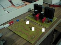
All the groundpoints input-ground input-ground from psu and output-ground has their own wire.I've now starpoint for groundconnection.The first thing I gonna try is to connect all groundwires to 1 point but wich one see pic
1 = input ground
2 = speaker outputground
3 = ground from PSU
What about using groundconnection 3?
In Belgium we may not connect in this case amplifier ground to the earth ground
Attachments
meanman1964 said:
In Belgium we may not connect in this case amplifier ground to the earth ground
Please explain.
In belgium we must make earth-grounding ourselfs.
The electricity cable comes into the house 3 or 2 wires but no earth-ground cable.We've to put in a copper bar into the ground and connect a wire to it that goes into the house for connecting our earthground.That's the reason.
The electricity cable comes into the house 3 or 2 wires but no earth-ground cable.We've to put in a copper bar into the ground and connect a wire to it that goes into the house for connecting our earthground.That's the reason.
Point number 3 seems reasonable. There you should terminate the PSU-ground (that is the wire from the minus-pin of the rectifier bridge) , the input-ground and the output ground.
I'd equip the chassis with a screw terminal similar to a speaker terminal. It should be firmly connected to the chassis. On the outside you connect your DIY earth-wire.
On the inside you connect each channel's star ground-point through a thermistor to that terminal.
This way the two channels' grounds don't see each other directly, thus eliminating potential ground loops.
For an example see page nine of http://www.firstwatt.com/downloads/f1_srv_man.pdf.
Don't forget to make twisted pairs.
And what is that third board?
- Status
- Not open for further replies.
- Home
- Amplifiers
- Pass Labs
- My first class A amplifier