Do you have an oscilloscope? Are you able to 'scope for the DATA and CLOCK Lines going to the DAC?
If no 'scope, can you take some DC readings on the DAC and Op-Amps?
I take it you've done some Modifications to the player. Can you list what you have done?
I don't think the Silmics will be the cause.
On your Mods, have been over your soldering to look for any solder splashes/short-circuits. It is sometimes easy to do this, especially when you're in a rush to listen to your latest changes. I'm guilty of this too !!!
Hello Percival,
Thank you again.
Well I bought this particular Marantz modded from the UK back in 2008, so this time all I did was:
1. replace the caps and diodes, and
2. as usual had to repair some tracks, and bridged some wire near the dac.
3. Also had to fix one of the legs of the flims on the dac
I have no scope though I can do readings if you tell me how to do them on the DAC and opamps. I assume the RCA would be earth?
Last edited:
OK. Any chance of some pics of the PCB, both sides?
Which Diodes have you replaced?
''....as usual had to repair some tracks, and bridged some wire near the dac.......'' Not sure what you mean here. Can you explain a little further?
''Also had to fix one of the legs of the flims on the dac'' Again a little explanation would be useful.
Anyway, yes, with DVM Black Probe on the RCA 0 Volts connection and with the Player playing can you go round the DAC and OP Amps Pin by Pin to see what we've got? DC Volts.
Hi Percival,
I have some pictures of the pcb
I replaced 12 diodes - all the larger ones in the PSU heatsink and the 4 outside the heatsink.
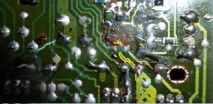
I had to fix some wire to bridge the broken tracks as seen in the pictures. The pin (leg of the films around the dac, i resoldered it back to the TDA pins.
What voltages on the DMM 200mv for around the DAC and Op Amps
First pic with red markings, not sure if wire is bridged as mulitmeter didnt show continunity
I have some pictures of the pcb
I replaced 12 diodes - all the larger ones in the PSU heatsink and the 4 outside the heatsink.
I had to fix some wire to bridge the broken tracks as seen in the pictures. The pin (leg of the films around the dac, i resoldered it back to the TDA pins.
What voltages on the DMM 200mv for around the DAC and Op Amps
First pic with red markings, not sure if wire is bridged as mulitmeter didnt show continunity
An externally hosted image should be here but it was not working when we last tested it.
An externally hosted image should be here but it was not working when we last tested it.
An externally hosted image should be here but it was not working when we last tested it.
An externally hosted image should be here but it was not working when we last tested it.
An externally hosted image should be here but it was not working when we last tested it.
An externally hosted image should be here but it was not working when we last tested it.
Hi,
Boy, I do not how you accomplished to do does soldering. One thing I would do it is try to clean the soldered area. That would allow you to see if you have solder bridges. Also I would used the schematic and pickup a point that allow you to check if you have a good connection for those components and the copper run that you soldered. It is a hard job but you will know if you have a good connection. I think you have a lot of patience. if I were you i would already dump it in the trash. Any way keep you hard work and see if you can make it to work.
Boy, I do not how you accomplished to do does soldering. One thing I would do it is try to clean the soldered area. That would allow you to see if you have solder bridges. Also I would used the schematic and pickup a point that allow you to check if you have a good connection for those components and the copper run that you soldered. It is a hard job but you will know if you have a good connection. I think you have a lot of patience. if I were you i would already dump it in the trash. Any way keep you hard work and see if you can make it to work.
OK. There's some pretty dubious soldering there. Some of which could be causing the problem.
Also, doing the 'Capacitor Mod' on the TDA1541, I thought the original SMD ones had to be removed(?). I'm not sure about this as I've never done this Mod myself. Anyway, if I were you I'd remove all the new Caps and tidy the DAC soldering. DO make sure you don't leave your Iron on there too long so you don't damage the IC.
I think you need to spend some time and check all that soldering.
Regarding the picture with the Red Dots, the Track actually goes underneath the SMD device to the pad to the left of the one dotted. (See my pic).
Anyway, if you think all the soldering is good then DC measure all the pins on the DAC and the OpAmps.
Attachments
Hi,
Boy, I do not how you accomplished to do does soldering. One thing I would do it is try to clean the soldered area. That would allow you to see if you have solder bridges. Also I would used the schematic and pickup a point that allow you to check if you have a good connection for those components and the copper run that you soldered. It is a hard job but you will know if you have a good connection. I think you have a lot of patience. if I were you i would already dump it in the trash. Any way keep you hard work and see if you can make it to work.
Hi Tauro
I have to have patience, as the CD50 come from the UK around 235$ AU all up, so I cant trash it, though a spare laser and dac maybe. Yes, i think my cheap iron is a hot one. I ran out of IPA cleaning stuff, so I better get some more. Thanks 🙂 True I should have done a little bit at a time and test
OK. There's some pretty dubious soldering there. Some of which could be causing the problem.
Also, doing the 'Capacitor Mod' on the TDA1541, I thought the original SMD ones had to be removed(?). I'm not sure about this as I've never done this Mod myself. Anyway, if I were you I'd remove all the new Caps and tidy the DAC soldering. DO make sure you don't leave your Iron on there too long so you don't damage the IC.
I think you need to spend some time and check all that soldering.
Regarding the picture with the Red Dots, the Track actually goes underneath the SMD device to the pad to the left of the one dotted. (See my pic).
Anyway, if you think all the soldering is good then DC measure all the pins on the DAC and the OpAmps.
Hi Percival
I bought this particular CD50 a few years back, i had to use it after the other CD50 board project didnt work. They are the orginal mods done around the TDA, but where i fixed a pin, maybe the solder is touching or messy, so will clean that up carefully, as well as other solder work, and get some IPA cleaning stuff. Thank you, I shall now see if i get continuity. with that track. After I check it all over I shall measure all the pins on the DAC and Opamp, if with any luck get it playing.
Hi Tauro and Percival
I did a quick check one of the legs of the films was loose on the TDA, i fixed it up, still no sound. This morning will make sure the opamp adaptor is firmly in place as its a bit raised
I did a quick check one of the legs of the films was loose on the TDA, i fixed it up, still no sound. This morning will make sure the opamp adaptor is firmly in place as its a bit raised
Marantz cd50 distored unclear audio after mod
Hi All
I finished finally my Marantz CD50, though i am only getting distorted sound in one channel and none in the other. I could not find my new opamps so i found some opamps in the part box? any case these are damaged hence the problem or another issue? anyone experience this after a mod?
Thank you
Sam
Hi Danico🙂Please, dont destroy any more vintage player.
They are good enough without mods.

 was already destroyed, help me save this vintage player, almost got it working
 Also my CD40 is perfect working with my mods, so i am very happy with that 😀 Only thing I have not done is the decouping capacitor on the TDA but i am afraid to damage it
Hi Danico🙂
Only thing I have not done is the decouping capacitor on the TDA but i am afraid to damage it
I would be afraid,too.
Believe me less messing around is the best.
I did just like you do.
Now I rather keep them very close to original. And having some separate dac board or only one player to abuse.
for me is a Revox B225 that just keeps playing and better sounding then my 1000$ dac.
I would be afraid,too.
Believe me less messing around is the best.
I did just like you do.
Now I rather keep them very close to original. And having some separate dac board or only one player to abuse.
for me is a Revox B225 that just keeps playing and better sounding then my 1000$ dac.
The Revox B225 is like a Marantz? TDA dac, i will have to google your player.
The CD40 is perfect after the mods, i did the capacitors, opamp, and NOS, nothing else, as i was afraid to damage the board, trying to put new diodes so left it out ! wow is very very good 😀 , i think less is best, leave the decoup around tda
The Revox are very delicate to work on. I mean you would destroy at your very first soldering attempt.

Not too much of the market and they are not the 50 $ category.
Better get yourself a TDA dac board, there are plenty of them
and play on those. you dont need to troubleshoot the whole player mech. if you mess up something.

Not too much of the market and they are not the 50 $ category.
Better get yourself a TDA dac board, there are plenty of them
and play on those. you dont need to troubleshoot the whole player mech. if you mess up something.
Hi Danico 🙂
Revox is not in the $50 category, i saw this player is worth a lot more.
Good idea a cheap tda board to practrice on. The links are loading but wont open.
Revox has the TDA1540 like the CD74/84. I have trouble with my CD74 at the moment. I will try to fix. i think the jumper cable is the problem. This old dac is very analog
- Status
- Not open for further replies.
- Home
- Source & Line
- Digital Source
- My first CD50 mod with NOS