Marantz CD50 bipolar replacement
I have bought another CD50,as some years ago I bought a modded CD50 with nos.
My question is, is is safe to use higher voltage and capacitances. On my other Marantz , they had 10v 220uf, 10v seems low
Thank you 🙂
Sam
I have 470uf 35v silmics on hand - 4 of them
I have bought another CD50,as some years ago I bought a modded CD50 with nos.
My question is, is is safe to use higher voltage and capacitances. On my other Marantz , they had 10v 220uf, 10v seems low
Thank you 🙂
Sam
I have 470uf 35v silmics on hand - 4 of them
is safe to use higher voltage and capacitances.
No problem if they fit. Just be certain of the polarities.
Thank you Ray,
I am going by how the MarantzCD50, which I bought modded, the polarities must be correct? unless the board is different, but should be the same since it's a CD50
I am going by how the MarantzCD50, which I bought modded, the polarities must be correct? unless the board is different, but should be the same since it's a CD50
An externally hosted image should be here but it was not working when we last tested it.
I am going by how the MarantzCD50, which I bought modded, the polarities must be correct? unless the board is different,
but should be the same since it's a CD50
Yes, that should be ok. Bipolar types are thought to sound better, BTW.
Thanks Ray, but the Elna SilmicII are better sounding than Nichicon, but making a bipolarp out of a non bipolar vs bipolar, the bipolar sounds better? If so i can go 3x the value with a Nicicon ES bp
Thanks Ray, but the Elna SilmicII are better sounding than Nichicon, but making a bipolarp out of a non bipolar vs bipolar,
the bipolar sounds better? If so i can go 3x the value with a Nicicon ES bp
Yes, likely because the one piece cap is more symmetric in construction.
I do have another marantz though its not a cd50 but a cd75MKII, there i went with 3x the value with the bp, and used ES, very nice sounding player, but my friends rave about this modded Marantz CD50 i bought, the one with the 2 non-biplars in the photo.
The ES bp is like 3x cheaper than the Elnas also. I had a look i can get 330uf 25v or 50v, verse the current bp which is 100uf 16v.
The ES bp is like 3x cheaper than the Elnas also. I had a look i can get 330uf 25v or 50v, verse the current bp which is 100uf 16v.
I purchased a Marantz CD50 recently, to mod, as a couple of years ago I bought modded NOS Marantz CD50 on ebay. I will closely be following this one, as I attempt the NOS, and recap.
I am still undecided on the output whether to keep the bp, and use 1000uf 16v or 470uf 16 ES, or go with non polar SilmicII 220uf or maybe 330uf 16v
Also since the 11DQ10 diode is no longer available, ive tried to find a subsitute, and narrowed it down ? which would suit from the list?
diode comparison
I am still undecided on the output whether to keep the bp, and use 1000uf 16v or 470uf 16 ES, or go with non polar SilmicII 220uf or maybe 330uf 16v
Also since the 11DQ10 diode is no longer available, ive tried to find a subsitute, and narrowed it down ? which would suit from the list?
An externally hosted image should be here but it was not working when we last tested it.
diode comparison
An externally hosted image should be here but it was not working when we last tested it.
Last edited:
Marantz CD50 NOS mod, no sound but buzz from speakers
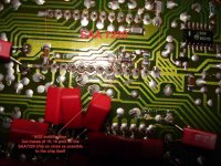
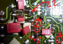
At first there was no sound, i checked the RCA sockets they are fine, then I wondered if the caps around the dac are touching?😕 or where i had to replace the black smd ceramic in psu, or maybe laser cable is not in properly, good news however player has no bang etc so caps all correct😀
TDA film caps? possible these are touching?
NOS mods
PSU ceramic (black replaced , due to me braking one with 22nf wima)
view of mods
At first there was no sound, i checked the RCA sockets they are fine, then I wondered if the caps around the dac are touching?😕 or where i had to replace the black smd ceramic in psu, or maybe laser cable is not in properly, good news however player has no bang etc so caps all correct😀
TDA film caps? possible these are touching?
An externally hosted image should be here but it was not working when we last tested it.
NOS mods
An externally hosted image should be here but it was not working when we last tested it.
An externally hosted image should be here but it was not working when we last tested it.
PSU ceramic (black replaced , due to me braking one with 22nf wima)
An externally hosted image should be here but it was not working when we last tested it.
view of mods
An externally hosted image should be here but it was not working when we last tested it.
Seeing your solder work wouldn't except any sound from this.😱
Fisrt of all learn how to solder properly https://www.youtube.com/watch?v=lMzJJYjtEHY
Those joints dont make much contact and even if they do they dont sound good.
Try to check for cold joint...... and then get rid off all the dac decoupling caps but the very first SMB.
Believe me less is more most of the time. 🙂
I use to do just like you many years ago, just take your time and you will learn a lot.
😱 Karma do works.
I just changed 2 caps in my Revox B225 and I cleaned the board at one cap but not the other. The result scratchy sound with buzzing on one side.😱
After cleaning it up everything back to normal. sound is improved greatly 🙂
I just changed 2 caps in my Revox B225 and I cleaned the board at one cap but not the other. The result scratchy sound with buzzing on one side.😱
After cleaning it up everything back to normal. sound is improved greatly 🙂
Hi Danico, thanks for the reply and help. That is bad luck, maybe i need to clean up my board also, might be some solder on it 🙂
Cleaning would help, for sure.
for the decoupling caps around the dac:
Those long legs hurt more then the cap could use.
i thing one bigger cap at the MSB would be enough. like 1uf. pin7 and 24
if you want to improve the sound,then connect 2x 6K8 resistors from the -15V to the DEM cap legs of the dac.
that will give you cleaner more focused sound better bass and highs.
Hi,
MSB is the most significant bit and there is a LSB least significant bit.
In a philips i2S MSB is the first bit in the digital sign and LSB is the last one.
Now this is a short answer, but to understand a bit of your dac you should do some more readings................🙄
I can highly recommend Ecdesigns topic, that is quite long tread,but even if you start reading it from the middle you will find many good infos and simple great solutions to improve your cd to a much higher level.
http://www.diyaudio.com/forums/digi...ding-ultimate-nos-dac-using-tda1541a-274.html
from Ecdesigns:
"The active divider decoupling caps do have clearly audible effect on sound quality. The decoupling caps need to have low inductance, very low leakage current, and low microphonics. Some of the active divider outputs have only half the ripple frequency (check TDA1540 datasheet), and the ripple currents vary with the output current.
So capacitors filtering fDEM / 2 need to have twice the capacity of the capacitor filtering fDEM. fDEM is typically around 200 KHz. Capacitors filtering lower currents also have lower ripple current to filter, so capacitance can also be lower. When selecting capacitor values with respect to DEM clock ripple current frequency and active divider output current, and using 1uF as maximum value, following would apply:
pin 13,18, 2mA, fDEM /2, 1uF
pin 12,19, 1mA, fDEM, half current (13,18), twice the frequency of MSB, 250nF
pin 11,20, 0.5mA, fDEM / 2, half frequency, half current (12,19), 125nF
pin 10,21, 0.25mA, fDEM, half current double frequency (11,20), 31.25nF
pin 9,22, 0.125mA, fDEM / 2, half current, half frequency (10,21), 31.25nF
pin 8,23, 0.0625mA, fDEM, half current (9,22), 7,8nF
pin 7,24, 0.0625mA, fDEM, equal current (8,23), 7.8nF.
In practice, 1uF (MSB), 220nF, 120nF, 33nF, 33nF, 8.2nF, 8.2nF. This would give equal ripple currents on all MSBs.
Active divider decoupling also depends on DEM clock. Like mentioned before, DEM clock oscillator is able to "lock" on (on-chip) BCK crosstalk. By selecting DEM clock capacitor values that produce (almost) exact multiples of fs, the DEM clock will "lock" to BCK and jitter amplitude would drop significantly. The often used 470pF and 680pF won't result in a "lock" and produce maximum DEM clock jitter amplitude."
Take your time and read a lot.
Attachments
Opps.
Before I gave you the wrong pin numbers for MSB. Correctly is pin 13,18.
Should have checked before writing. 🙂 everything else is correct though.
Before I gave you the wrong pin numbers for MSB. Correctly is pin 13,18.
Should have checked before writing. 🙂 everything else is correct though.
Attachments
Last edited:
Hi Danico,
Thanks for the information and link, yes a lot to take in 🙂
Still trying to sort fault , took out the flim around the dac, cleaned it up, and buzz still.
Thanks for the information and link, yes a lot to take in 🙂
Still trying to sort fault , took out the flim around the dac, cleaned it up, and buzz still.
- Status
- Not open for further replies.
- Home
- Source & Line
- Digital Source
- My first CD50 mod with NOS