Hi Tony ,
Could you have a look at post #13 and # 15 at the following link .
http://www.diyaudio.com/forums/subwoofers/254327-subwoofer-dayton-audio-sd270a-88-dvc-2.html
and also the attachments of the posts so that I may have your comments. Its the sub i planning to build.
regds
prasi
Could you have a look at post #13 and # 15 at the following link .
http://www.diyaudio.com/forums/subwoofers/254327-subwoofer-dayton-audio-sd270a-88-dvc-2.html
and also the attachments of the posts so that I may have your comments. Its the sub i planning to build.
regds
prasi
Hi Tony,
another query and this question is regarding my bookshelf (converted to floor standing at the last moment!).
If I understand correctly, below the ported box tune frequency, the cone excursion will increase at a very high rate.
In this case, how do I protect the woofer? is there any High pass circuit which can cut off subsonic frequencies (1/2 octave below box Tuning Frequency).
Fortunately, till date I haven't gone past 30% of volume on my 25W per channel amp. Even at such low level, the sound is room filling and very satisfactory.
However, in case, accidentally someone turns the knob all the way up, is there a chance that woofer might get damaged due to low frequencies?
regards
prashant
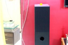
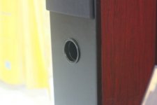
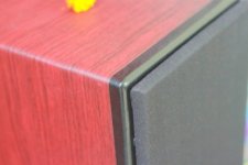
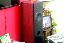
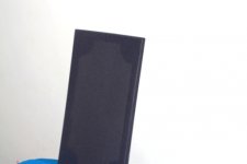
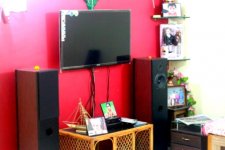
Also I wanted share the photos of the floorstaning speakers that you greatly helped in building. Cant thank you enough..
prashant
prashant
Attachments
Hi David,
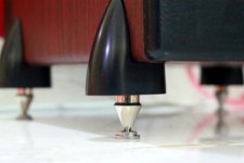
Thanks for the complements. I got the feet from a local diy store...
reg
prasi
P.S. Here is link for the design http://theaudiocrafts.com/index.php?route=product/product&path=59_69_112&product_id=176
Thanks for the complements. I got the feet from a local diy store...
reg
prasi
P.S. Here is link for the design http://theaudiocrafts.com/index.php?route=product/product&path=59_69_112&product_id=176
Last edited:
Hi Prasi, very nicely done! 🙂
with respect to the high pass, I think the most practical approach is to have an active high pass filter in your amplifier. This may prove difficult though if you have an intergrated amp. Many amps of old had "rumble filters" Which filtered out frequencies below 20Hz (which tended to come from turntables). You obviously need somewhat higher than that. As you are building a sub though your crossover/processor for the sub should take care of that hopefully.
I can't remember your speakers impedance, but just as an example a textbook first order high pass at 60Hz requires a capacitor around 330uF for an 8 ohm load and 660uF for a 4 ohm load, so you can see why active is preferable!
Tony.
Hi Tony thanks,
For the sub I am planning to use dayton audio spa 250 subwoofer plate amplifier. Here is the link. Dayton Audio SPA250 250 Watt Subwoofer Amplifier | 300-803. the amp has provision for both low level and high (speaker) level inputs.
The documentation says ,only if I use high level inputs on the plate amp then the output will be shaped by 1st order crossover of 125Hz for main L/R speakers. this obviously is a preferred option to solve the issue.
Now the question is how do I protect my main speaker woofer until the sub is done /sub is built but not being used? In this case if i have to use the cap then where to put it? between amp and crossover circuit or between crossover and woofer? The woofer's impedance is 8 ohm and I do not know if crossover modifies the impedance when looking from the amplifier.
Also will this cap affect main crossover circuit in any way?
lots of questions;-)
regds
prasi
Hi prasi, you are getting into territory I am unfamiliar with 🙂 in a band pass circuit the high pass comes first followed by the low pass so it definitely needs to go before the woofers crossover components.
Now this is where I'm uncertain. The cap will also introduce 90 degrees of phase shift so the question is do you put it in front of the high pass circuit for the tweeter as well to keep the overall phase the same... a reaaly big cap like that in series with a small cap will be pretty close in value to the original small cap.
you will likely need to use non-polar electrolytics, as film caps that big are very large and very expensive. whether you will hear a degradation in sound quality is hard to guess.
Note that the values I gave were purely for example and I didn't check your box tuning freq.
I've never actually blown a woofer before, but I have blown plenty of tweeters. I suspect your tweeters are more at risk from the too high a volume level than your woofers are 😉
edit: Just looked at the spec for the plate amp, and the HP outputs are basically just 220uF electrolitc caps in series with the output (for 90Hz at 8 ohms) So in my oppinion if that is the route you go, you would be better off sending line level stereo to the plate amp and just putting the caps in your speaker leads to the main speakers 🙂
Tony.
Last edited:
Hi Tony,
Thanks.
Let me tell you what I did. I downloaded the woofer box and circuit designer from Loudspeaker Design Software.
In the filter section I disabled all filters except high pass filter and set it to 41 Hz and filter type as first order butterworth to get 6 dB/octave slope to simulate our high pass cap. Even though the peak cone excursion gets tamed at lower frequencies, it is still way above Xmax.
However when I set the frequency to 80 Hz, the peak cone excursion is always below X-max. This would be a possible solution to avoid distortion.
If I have to use filter at such high frequency, does this imply that there is NO added benefit of building ported floorstanders (for me) as the very purpose was to get low end extension?
another query, to be doubly sure, the large cap would be inline on the red wire (+ve) between amp out and crossover, am i right?
Another thought; reversed tweeter polarity should not have any effect, right?
regards
prashant
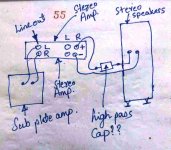
ignore # 55 on the sketch...its just a serial number of the memo pad... and sorry for the poor drawing🙂
p.s. the view in sketch is when i am standing and looking from the back side of my set up...
p.s. the view in sketch is when i am standing and looking from the back side of my set up...
Last edited:
Hi Prasi, the way you have drawn it seems ok to me. Yes you are going to loose low end if you make the filter higher. It is really only appropriate when you have the sub.
See if you can find the X-Mech spec for the speaker. X-Max is the maximum travel whilst staying linear (ie low distortion) X-Mech is the maximum excursion without damage.
Also what frequency are you going to cut the subs in at? Something pretty low I assume. I've no experience with separate subs. What I am planning myself is stereo subs separate 2 channel amp to drive them and custom electronic crossover tuned to give good blending between the "subs" and the main speakers. I put subs in quotes as they in reality will only go down to about 30Hz and will be playing up to 300Hz.
Tony.
Hi Tony,
Yes you are right, I will have to use the cap only when the sub is built. It would be a good idea I guess, to make a seperate small box with capacitor with banana plugs at input and outputs, so that it can be just plugged in / out as and when required. Dont have the X-mech figure for the woofer. Can I take 15% - 20% over X-max as cone overdrive?
I plan to play with the cut-off freq of sub until the blend is perfect. By the way, the plate amp also has a phase reverse switch and bass boost , so plenty of settings to play around with.
In your case, you will be having active crossovers for each sub? and will they have variable frequency cut-off? That would be an interresting and educating build.
Prasi
P.S. for 80 Hz filter I need 250microF cap, right? and since such a big non-polarized cap is not available, I will put them in parallel and measure the resultant capacitance by a multimeter, am I right in doing so?
Last edited:
Hi Prasi, I actually don't know how much you can take over X-MAX I tried searching for some speakers with X-Mech specs (I have seen it before) but couldn't find any. From memory x-mech could be significantly higher than X-MAX, but I think it would be very speaker dependent.
Yes I am going to do an active crossover which will have low pass and high pass, and I intend to design the filters to blend perfectly (using measurements of the speakers).
I will have two 2 channel amplifiers. One for the subs (my old 100W / channel mosfet amp) and one for the main speakers (initially my gainclone but will probably end up being a BA3.
This is the online filter calculator I use when I want text-book values Crossover Design Chart and Inductance vs. Frequency Calculator(Low-pass) and yes 250uF is ok for 80 Hz and 8 ohms.
Yes if you need to put together 2 caps put them in parallel. You should probably go for minimum 50V rating on the caps as well.
Tony.
Hi Tony,
thanks for the info....
Now, do you remember some posts ago I asked you about the best possible way to attenuate the tweeter... You asked me to put a series resistance before tweeter crossover components, which will not affect xover frequency.
I have come up (thro internet search) with some contradicting and new (atleast to me) information...
crossover components see the load as it presented to them by the driver and combination of series and parallel leg of L-pad...
hence most L-pad calculators on-line, the net impedence (in ohms) (consisting of tweeter impedance and resistive components of L-pad) is equal to the value of impedance used to calculate the tweeter crossover capacitance and inductance. It has been thoroughly discussed by experts in the crossover sticky article that placing the resistor before twtr xover may not ba good idea. and after xover it most certainly affects xover (as informed by you).
here is an interesting and probably old article.....Passive Crossover Network Design
jump over to Attenuation networks, if you have time constraint...
Its a very interesting article and in some way contradicts AllenB's crossover tutorial (as far as tweeter crossover components with L-pad circuits are concerned)
I have a posed a question to AllenB in the sticky post and awaiting his reply.
reg
prasi
Last edited:
Interesting, I have read that article before but obviously the part about where to place the attemuation didn't sink in (at least only the fact that it changes the crossover transfer function if after the network stuck)
I'll have to go back to my sims and see what difference re-positioning the pad resistors makes on my crossover. It may actually give me a slightly friendlier impedance in the low pass section. I'd never actually considered the fact that it was operating accross the frequency range.
I guess when using just s series resistor before is probably better but with an l-pad it makes sense for it to be after.
Tony.
Hi Tony,
I have modified my crossover based on the suggestions received from Lojzek and others in the sticky thread on crossovers without measurements. My speakers are sounding much better. I have used BOXSIM by visaton for simulations. It is a very nice program and very simple to use and it gives the effect of changing the components in xover instantly on your F-R and Phase. pl have a look at my posts on that thread if time permits.
Now I have two very basic questions and I will be glad if you answered.
1.How much tolerance on phase tracking at xover is considered acceptable.? In the simulations I made, there appears to be 20 deg. phase shift , although with correct polarity the amplitude is more or less flat at xover and there is deep symmetrical null when polarity is reversed.
2. how SPL variation over the entire frequency range is acceptable (say +/- 2dB from saay 100Hz to 20kHz).
Ofcourse I know all the simulations are meaningless without measurement but....
Also there is an impedance and T/S measurement equipment available in India Dayton make Dayton Audio - DATS Dayton Audio Test System ... do you think I should invest in it.
regds
Prasi
Attachments
Hi tony,
some exciting findings...
In addition to the above simulation, I just measured the polarity of the speaker with Holm impulse . attached is the image. Blue is the polarity reversed on the left speaker which shows a deep null and the phase difference is about 170 degrees and green is the correct polarity of the right speaker which is flat at xover frequency and phase difference is about 5 degrees ( ideally it should have been 10 degrees but as I said above the reversed polarity measurement is with left speaker and correct polarity measurement is with right speaker: so may be speaker to speaker variation and measurement inconsistencies).
again the measurement is with web cam mic and dont pay attention to the dips above 2000Hz as they are probably due to mic quality as you had indicated to me earlier.
I think this time i got the xover circuit correct as the first version did have this deep null when polarity was reversed ( you had raised your concerns on the absence of deep null when I had shared the measurement earlier)
regards
prasi
- Status
- Not open for further replies.
- Home
- Loudspeakers
- Multi-Way
- My First Bookshelf Project