Well, here it is:
http://www.darkmatter.myby.co.uk/cascodevas.png
(I didn't make it an image as it's huge - LTSpice looks nasty at smaller resolutions)
I've never really designed an amplifier before, and haven't had a lot to go on, just some articles on the internet, looking at lots of designs, and tinkering in SPICE, so I'm looking for some expert opinions here.
A few points:
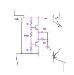
* 2SC2240/2SA970 will most likely be replaced with 2SC2547E/2SA1085E instead as they are lower noise. 2N5401/2N5551 will probably be used for early testing as they are cheap!
* BD139/140 are on the edge of their ratings, I will hopefully use 2SC2911/2SA1209 instead.
* MJL21193/MJL21194 will probably be changed for MJL4281/MJL4302 - I didn't use the SPICE models for those as they are apparently wrong.
One question I do have, there is a large turn-on thump due to the current sources in the input LTP's... is there any way I can calm this down as it takes about 2 seconds to settle according to the simulator.
It's designed for 100W at 8 ohms with a 1V RMS input (gain 30.46dB)
http://www.darkmatter.myby.co.uk/cascodevas.png
(I didn't make it an image as it's huge - LTSpice looks nasty at smaller resolutions)
I've never really designed an amplifier before, and haven't had a lot to go on, just some articles on the internet, looking at lots of designs, and tinkering in SPICE, so I'm looking for some expert opinions here.
A few points:
* 2SC2240/2SA970 will most likely be replaced with 2SC2547E/2SA1085E instead as they are lower noise. 2N5401/2N5551 will probably be used for early testing as they are cheap!
* BD139/140 are on the edge of their ratings, I will hopefully use 2SC2911/2SA1209 instead.
* MJL21193/MJL21194 will probably be changed for MJL4281/MJL4302 - I didn't use the SPICE models for those as they are apparently wrong.
One question I do have, there is a large turn-on thump due to the current sources in the input LTP's... is there any way I can calm this down as it takes about 2 seconds to settle according to the simulator.
It's designed for 100W at 8 ohms with a 1V RMS input (gain 30.46dB)
The best thing to do is build it and see what happens.
The output section looks solid -- EF topology has is pretty trouble free once you get the bias setting stable. However, I question whether you need a tripple unless you plan to parrallel more output devices in a subsequent version.
I notice the base resistors on the differential pairs. I'm not sure if I see this often. What is the intent/purpose? Regarding the 970/2240s in the VAS cascode -- I've had a situation in the past where high hfe transistors in those positions contributed to instability in the VAS. Substituting a considerably lower hfe transistor improved the situation with no increase in measured distortion (ltspice predicted otherwise).
In any case build it. Unless you are very, very experienced the odds of getting it right the first time are slim no matter how much simulating you do. Just get it stable and functional at first even if you have to accept higher THD than you want. It's really hard to opyimize an amplifier that keeps trying to commit suicide.
The output section looks solid -- EF topology has is pretty trouble free once you get the bias setting stable. However, I question whether you need a tripple unless you plan to parrallel more output devices in a subsequent version.
I notice the base resistors on the differential pairs. I'm not sure if I see this often.
What is the intent/purpose? Regarding the 970/2240s in the VAS cascode -- I've had a situation in the past where high hfe transistors in those positions contributed to instability in the VAS. Substituting a considerably lower hfe transistor improved the situation with no increase in measured distortion (ltspice predicted otherwise).In any case build it. Unless you are very, very experienced the odds of getting it right the first time are slim no matter how much simulating you do. Just get it stable and functional at first even if you have to accept higher THD than you want. It's really hard to opyimize an amplifier that keeps trying to commit suicide.
sam9 said:The best thing to do is build it and see what happens.
Hopefully I shall be able to do this soon...
sam9 said:The output section looks solid -- EF topology has is pretty trouble free once you get the bias setting stable. However, I question whether you need a tripple unless you plan to parrallel more output devices in a subsequent version.
Basically I'm being influenced by the Leach amplifier... the Triple Darlington seems to have a lot of advantages, and it had lower crossover distortion when I tested it in LTSpice. I stayed away from CFB after doing a smaller amplifier and finding that the CFB is murder to keep stable.
sam9 said:I notice the base resistors on the differential pairs. I'm not sure if I see this often.
Again see Leach amplifier. My thought on this was that it provides some base stopper isolation between the two halves of the circuit.
sam9 said:Regarding the 970/2240s in the VAS cascode -- I've had a situation in the past where high hfe transistors in those positions contributed to instability in the VAS. Substituting a considerably lower hfe transistor improved the situation with no increase in measured distortion (ltspice predicted otherwise).
Noted. I have seen a mix of things done with cascodes... some use two small signal devices, some a small signal and medium power device, and some use dual medium power devices.
sam9 said:In any case build it. Unless you are very, very experienced the odds of getting it right the first time are slim no matter how much simulating you do. Just get it stable and functional at first even if you have to accept higher THD than you want. It's really hard to opyimize an amplifier that keeps trying to commit suicide.
The big problem is that as of yet, I don't have a 'scope, so if it starts oscillating or doing other wierd things I have no way to track it down. This is why I'm keeping my eye on eBay for a good 50MHz dual channel 'scope 🙂
Hi Jaycee,
a twin beam scope would be even better. No chopping between channels because it has two completely separate channels all the way from input to the spot on the CRT. It might then have twin channel on each beam.
a twin beam scope would be even better. No chopping between channels because it has two completely separate channels all the way from input to the spot on the CRT. It might then have twin channel on each beam.
I have found that the Leach sounds better with resistors for the current sources for the diff pairs rather than an active current source.
It also sounds better with less gain in the diff pairs as in the V4.5
It also sounds better with the nested FB loop to the pre-drivers
The main reason the Super Leach has a cascoded VAS is for power handling, it is not needed for smaller versions.
"I have been asked why I did not use cascode stages (common emitter followed by common base) for the second stage. The cascode stage minimizes the Miller effect and exhibits a lower input capacitance than the common emitter stage. It is used in applications where bandwidth is to be optimized. A feedback amplifier, however, must have a dominant pole to set its gain bandwidth product. It can be shown that the optimum method to set this pole is to place a capacitor from output to input of the highest gain inverting stage. If I had used cascode amplifiers in the second stage, a capacitor would have to be placed from the output to the input of each to set the dominant pole. Then the cascode stage would have the same bandwidth as the common emitter stage. A cascode stage cannot be used to improve the bandwidth of a feedback amplifier if the gain bandwidth product is to be held constant. If the gain bandwidth product is not intentionally limited to some reasonable value, the amplifier would not be stable. That is, it would oscillate. "
I'm keeping my eye on eBay for a good 50MHz dual channel 'scope
I don't know your budget but consider this
http://www.elexp.com/tst_s500.htm
It's not the equivalent of an HP ot Techtronics but it is a lot of capability for the price.
I wan't thinkinf Tripple-EF vs CFB. I agree CFB can be a pain - similar experience to you. I was think of a simpler EF just drivers and output devices.quote:
Originally posted by sam9
The output section looks solid -- EF topology has is pretty trouble free once you get the bias setting stable. However, I question whether you need a tripple unless you plan to parrallel more output devices in a subsequent version.
Basically I'm being influenced by the Leach amplifier... the Triple Darlington seems to have a lot of advantages, and it had lower crossover distortion when I tested it in LTSpice. I stayed away from CFB after doing a smaller amplifier and finding that the CFB is murder to keep stable.
AndrewT said:Hi Jaycee,
a twin beam scope would be even better. No chopping between channels because it has two completely separate channels all the way from input to the spot on the CRT. It might then have twin channel on each beam.
This is what I meant, I think... "dual trace" is what I meant, but yeah, one capable of displaying 2 traces at once.
sam9 said:I don't know your budget but consider this
http://www.elexp.com/tst_s500.htm
It's not the equivalent of an HP ot Techtronics but it is a lot of capability for the price.
I've looked at PC based scopes before, the Velleman one isn't too bad from what I've heard, and BitScope is interesting... but they're still out of my price range compared to an analogue 'scope from eBay which can go for around the £100-130 mark.
Hi jaycee
It looks pretty standard and surely will work nice.
One thing I've noticed is you have low feedback factor, so you will have to run minimum 50mA output stage bias to keep Xover distortion low.
Another thing is why you are using miller compensation combined with cascode. It deosn't make sense to me, as cascode is made to (besides of dissipation issues) eliminating miller effect. Why don't you use a complementary Vbe multiplier with midpoint to the ground thru 23.5k R instead of these two 47k. You can also put a cap parallel to this 23.5k R to place a dominant pole instead of miller. hm...?
regards
Originally posted by darkfenriz
One thing I've noticed is you have low feedback factor, so you will have to run minimum 50mA output stage bias to keep Xover distortion low.
Are you referring to the global feedback of 30.46dB or the fact that there is no local feedback between the drivers/predrivers and the outputs?
Originally posted by darkfenriz
Another thing is why you are using miller compensation combined with cascode. It deosn't make sense to me, as cascode is made to (besides of dissipation issues) eliminating miller effect.
I was getting ringing on the edge of a 1KHz square wave without compensation. I am wondering whether using RC filters would be better as I have seen in a number of designs
Originally posted by darkfenriz
Why don't you use a complementary Vbe multiplier with midpoint to the ground thru 23.5k R instead of these two 47k. You can also put a cap parallel to this 23.5k R to place a dominant pole instead of miller. hm...?
I'm no big expert. So i'm not sure what you mean here.
20 log ((22000+680)/680) = 30.46dB correct?
Ah, I have seen that VBE design before on a schematic I have. It doesn't seem very common and my tries at making it behave in the simulator were unsuccessful so i stuck with the single transistor. I chose MJE340 because it's a cheap TO126 device that can be easily coupled to the main heatsink.
Ah, I have seen that VBE design before on a schematic I have. It doesn't seem very common and my tries at making it behave in the simulator were unsuccessful so i stuck with the single transistor. I chose MJE340 because it's a cheap TO126 device that can be easily coupled to the main heatsink.
jaycee said:20 log ((22000+680)/680) = 30.46dB correct?
Ah, I have seen that VBE design before on a schematic I have. It doesn't seem very common and my tries at making it behave in the simulator were unsuccessful so i stuck with the single transistor. I chose MJE340 because it's a cheap TO126 device that can be easily coupled to the main heatsink.
Please excuse me if I am wrong but I think that's the expression of the gain of your amplifier. For an amplifier having feedback factor B, its closed loop gain will be 1/B as you calculated (providing direct gain is very high). So, in your case, we would have:
20 log (680/(680+22000)) = -30.46 dB
Absolute value is the same but with the detail of a sign. It seems consistent. What do you guys think ?
Best regards,
João Pedro
Hi jaycee,
i would strongly suggest you to putting Q15 /Q16 before R51/R52, cause the voltage output stage is very sensible and hf coupled over Ccb with the main supply. even better: remove R51/R52 and use a separate power supply.
greetings.
i would strongly suggest you to putting Q15 /Q16 before R51/R52, cause the voltage output stage is very sensible and hf coupled over Ccb with the main supply. even better: remove R51/R52 and use a separate power supply.
greetings.
and something more:
the output transistors have a poor bandwidth (> 4 mhz) (and r31-r34 are quiet large too) so i would suggest to use a 2 pole frequency compensated design with a c @r1/r3.
or probably better use high bandwith sanken transistors and one pole and you don't need the output coil. much easier to control too.
i would never put electrolytics in signal path too. use on chip transistors at input stage and maybe fets: 2sk389 / 2 sj 109.
greetings.
Reina said:i would strongly suggest you to putting Q15 /Q16 before R51/R52, cause the voltage output stage is very sensible and hf coupled over Ccb with the main supply. even better: remove R51/R52 and use a separate power supply.
Hmm yes those predrivers could go before the resistors and thus get the advantage of running from a smoother supply. I did think about using seperate supplies (I may even fabricate the board so that this is easily possible) but it means having a more complicated PSU.
Originally posted by Reina
the output transistors have a poor bandwidth (> 4 mhz) (and r31-r34 are quiet large too) so i would suggest to use a 2 pole frequency compensated design with a c @r1/r3.
or probably better use high bandwith sanken transistors and one pole and you don't need the output coil. much easier to control too.
The output transistors will actually be MJL4281/4302, MJL21193/21194 are shown because the models for the 4281/4302 seem to be unreliable. These parts have an fT of 35MHz. Sankens are very expensive and I cannot afford them, especially as I can order the MJL's as samples for very cheap.
Originally posted by Reina
i would never put electrolytics in signal path too.
I presume you mean C1 and C3. C3 will be a polypropylene or polyester capacitor if I can find them. C1 would be a nonpolarised electrolytic but I may consider a servo at some point that adjusts DC offset by adjusting the current sources.
Originally posted by Reina
use on chip transistors at input stage and maybe fets: 2sk389 / 2 sj 109.
It's too difficult to source that kind of part here, especially FETs as I have already looked for those for a headphone amplifier project. When I do find them again they are very expensive.
hi jaycee,
in germany this is not such a problem. contact me, if you can't buy...
www.segor.de
2SK389 3,80 Euro
2SJ109 3,00 Euro
2SC3284 Sanken 4,20 Euro (150V 14A 125W 60 MHz)
2SA1303 Sanken 3,30 Euro
www.schuro.de
2SK389 BL 1,72 Euro
2SJ109 BL 2,52 Euro
2SC2922 Sanken 4,18 Euro (180V 17A 200W 50MHz)
2SA1216 Sanken 4,18 Euro
greetings.
Hi jaycee,
Would you mind posting the .asc spice file for your amplifier? I'm interested in seeing how it simulates.
Cheers,
Jon
Would you mind posting the .asc spice file for your amplifier? I'm interested in seeing how it simulates.
Cheers,
Jon
Hi jaycee
feedback factor is simply open loop gain divided by closed loop gain.
In your case it is pretty low, so THD won't be in order of 0.01% unless you take much care about open loop linearity and output stage biasing.
On the other hand you will have less problems with stability, TIM and other nasty things.
Build it and listen.
It should sound different from common high feedback amps.
Reina
You mean output transistors have low ft?
Does it affect the frequency responce and change the compensation circuit needed?
I don't understand. Output is just followers, which work like followers and it doesn't matter if beta of tripple darlington is 2 000 000 or 'only' 20 000. Especially with VAS with resistor to ground. Correct me if I am wrong.
best regards
- Status
- Not open for further replies.
- Home
- Amplifiers
- Solid State
- My first amplifier design