Hi folks,
i am looking into building my first amp ever, and even after much research, i'm still very confused 🙂 I know next to nothing about electronics, and would like a sanity check before buying stuff that won't work 🙂
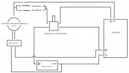
The idea is to build a small mono speaker with the amp inside, with a jack 3,5 and an on/off/volume switch. on top of that i want to add a usb port for charging phones when portable on 12v battery, or connect a chromecast audio for when i'm using it at home plugged to grid with a 12v dcconverter.
I drew a schematic of what i think should work, but have a few questions. feel free to draw on my schematic for clearer explanations.
Parts:
Sure Electronics' webstore 1 x 30 Watt Class D Audio Amplifier Board - TPA3110
speaker is a 30W 8ohm (might change it with a 4ohm)
10k logarithmic potentiometer with switch
UBEC somthing like this https://www.adafruit.com/product/1385
questions:
1) if the amp is 30W (8-24V), hook it up to 12V and crank up the volume to max. will it then simply draw the needed Amperes to reach 30W (30/12 = 2,5)? trying to figure out what kind of power supply to get.
2) is it possible to use a potmeter as shown in the schematic? i was told that most potmeters can't handle much power, so i would need a power relay to switch everything on.
2A) if i need a relay, how do i make sure that it's the right one?
2B) if i need a relay, how will everything power on if the chromecast is powered through the usb? and would the signal from a phone be enough to trigger the relay.
3) does it make any sense or am i going to burn down the thing, along with my house 🙂 anything missing or better solutions?
Thanks in advance for any reply, looking forawrd to build this thing. I'll keep you updated on the process.
Seb
i am looking into building my first amp ever, and even after much research, i'm still very confused 🙂 I know next to nothing about electronics, and would like a sanity check before buying stuff that won't work 🙂
The idea is to build a small mono speaker with the amp inside, with a jack 3,5 and an on/off/volume switch. on top of that i want to add a usb port for charging phones when portable on 12v battery, or connect a chromecast audio for when i'm using it at home plugged to grid with a 12v dcconverter.
I drew a schematic of what i think should work, but have a few questions. feel free to draw on my schematic for clearer explanations.
Parts:
Sure Electronics' webstore 1 x 30 Watt Class D Audio Amplifier Board - TPA3110
speaker is a 30W 8ohm (might change it with a 4ohm)
10k logarithmic potentiometer with switch
UBEC somthing like this https://www.adafruit.com/product/1385
questions:
1) if the amp is 30W (8-24V), hook it up to 12V and crank up the volume to max. will it then simply draw the needed Amperes to reach 30W (30/12 = 2,5)? trying to figure out what kind of power supply to get.
2) is it possible to use a potmeter as shown in the schematic? i was told that most potmeters can't handle much power, so i would need a power relay to switch everything on.
2A) if i need a relay, how do i make sure that it's the right one?
2B) if i need a relay, how will everything power on if the chromecast is powered through the usb? and would the signal from a phone be enough to trigger the relay.
3) does it make any sense or am i going to burn down the thing, along with my house 🙂 anything missing or better solutions?
Thanks in advance for any reply, looking forawrd to build this thing. I'll keep you updated on the process.
Seb
Attachments
you should be able to use a standard automotive relay.
the pot will only switch the signal line to the relay, so low amps.
then you run the amplifier and the 5v regulator from the relay.
the pot will only switch the signal line to the relay, so low amps.
then you run the amplifier and the 5v regulator from the relay.
cool, thanks, that's what i thought, but what if i have a chromecast driven by the 5v as signal input? i guess there won't be any signal to turn on the relay, so the relay needs a signal from something else right?
the relay just needs a 12v switched power.
the pot has seperate signal for audio, and switch for power.
the relay would then power the amp and 5v usb at the same time.
the pot has seperate signal for audio, and switch for power.
the relay would then power the amp and 5v usb at the same time.
OK, so i guess my next question is, where and how do i hook the relay in the system? I would love if someone could draw it in the schematics 🙂
I have a similar board

I use a raspberry pi zero with mpd for audio library from my NAS and for internet radio stations, and also use as a multiroom speakers using snapcast (I have 3 of these).
The raspberry pi runs 24/7. For turn off the speaker I use the stanby pins of the board, the consumption of the amp is near 0mA.
I use a 12V 3A external power supply for the amp and a DC-DC LM2596 power Supply step-down board to obtain the 5V for the raspberry pi.
For turn off the amp its necessary to ground the STBY pin. To do this could be done with the potentiometer switch. I do it directly with a gpi from the rassberry controlled remotely from an app or automatically in the absence of audio.
It has many possibilities.
Last edited:
- Status
- Not open for further replies.