Hi,
I now have all the part to builds my first amplifier based on Aren van Waarde’s design.
I am planning to have the amp and the PSU has two separate ‘box’. I am trying to find a good layout (both good to look at from the outside and easy to wire inside). However, there are still a few thing that are unclear. I understand that using star grounding is better: a single point as the ground and all components connected to the ground on the schematics have a wire straight to that point.
1-Where shall I place that point? Where it is going to be the simplest to wire or closest to a specific component?
2-If my PSU and amp are two separate box can I have to star point? Do they need to be connected in a specific way?
3-Is the star point supposed to be connected to the chassis? Why? What if the chassis is wood instead of metal?
4-Last but not least what shall I do with the main earth wire? Connect it to the PSU start point? To both start point? Directly to the chassis? Or to the chassis using a capacitor?
5-Finally, are there any pitfalls to look for?
Hello jerome,
maybe this article will help you:
http://www.aikenamps.com/StarGround.html
Good luck!!!
maybe this article will help you:
http://www.aikenamps.com/StarGround.html
Good luck!!!
I keep all B+ power supply grounds & filament grounds to one point, all cathode resistor grounding points to another and all signal grounds (input and output) to yet another, and then joining these three at one place (I chose the chassis earthing point) gives absolutley zero hum on my amp. However, mine is PP so maybe a little less sensitive to it?
The theory is that AC ground, DC ground and signal ground should be kept as separate as possible as they tend to interfere with each other and cause induced noise.
Also I use DC for the heaters in the first stage of the preamp, which probably helps. I would use it for all preamp stages, but my transformer gets a bit hot with the added cureent draw.
For your project, (by the way why have two separate chassis?) you could run two grounding wires to the power supply, one for AC and one for DC, which would link at the power chassis. 😕
Basically try it and see?
TG,
I have read the three following web sites and to be honest I feel even more confuse.
http://www.aikenamps.com/StarGround.html
http://www.geofex.com/Article_Folders/stargnd/stargnd.htm
http://www.mc-h.demon.co.uk/homepage.html
For all of the questions I first posted I am still wondering what to do
ShiFtY,
-------------------------------------------------------------------------------- I keep all B+ power supply grounds & filament grounds to one
point, all cathode resistor grounding points to another and all
signal grounds (input and output) to yet another, and then
joining these three at one place (I chose the chassis earthing
point) gives absolutley zero hum on my amp. However, mine is
PP so maybe a little less sensitive to it?
The theory is that AC ground, DC ground and signal ground
should be kept as separate as possible as they tend to
interfere with each other and cause induced noise.
--------------------------------------------------------------------------------
Ok, so basically instead of having all the parts connected to the ground by a single wire to a common point. I should have several points:
1 for High Voltage power and filament power
1 for cathode resistor
1 for signal ground on input and output
Then I should join those together at a fourth point
Is that right?
--------------------------------------------------------------------------------
For your project, (by the way why have two separate
chassis?) you could run two grounding wires to the power
supply, one for AC and one for DC, which would link at the
power chassis.
--------------------------------------------------------------------------------
I wanted two chassis just so that The power supply could be away from the amp, hence having only the amp showing but that was only (at first) for having a better looking system.
About this wiring between the Amp and the PSU I am not sure I understand what you mean? Basically I just want to understand what should be done and what should be avoided based on everybody’s experience
Thanks for your help
Jerome
Then I should join those together at a fourth point
That is what works for me.
I actually have all the filter cap -ve and the centre tap from the B+ transformer as the power supply ground;
the filament grounds as another;
the cathode resistors as another;
and the signal grounds (in and out) as yet another.
These are all connected at a single point on the chassis, in my case I chose the mains earthing point for the case.
Maybe the way I did it was overkill, but it only needs a few extra wires, takes about 10 minutes to solder up... and NO HUM!
To answer some of your questions, a metal chassis should be connected to ground to give shielding against stray electromagnetic/RF fields. If it is wood, you may possibly get some more hum. The main earth point should be connected to your household earth for safety. I did not need a capacitor there, YMMV.
You could run two cables from the PS to the amp, one with B+ (DC) and one with filaments (AC) and let each have their own ground return wire. However I still think transformers look cool if you paint them up, plus if you use a tube rectifier they look nice. Why hide em!
Basically just try different things till it is silent! There are no set rules, just different ideas...
Perhaps a good idea would be to get your schematic, and a few coloured pens, and mark the power grounds with one colour, the signal grounds with another, etc. Then, when you build it, you can easily see which ones to connect together.
As far as the circuit goes, can you give us a description of it?
Thank for those advice ShiFtY. Part of the reason why I will have two separate box is also because at first I probably won’t be able to afford a power supply with tube Rectifier. So, I might build a simple one with Diodes etc and in the future build a nice looking one with tube and transformer showing to replace it.
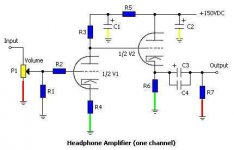
About the Schematics here it is it is fairly simple (I believe) it is mainly why I choose it. I did not want to go for something to complicated and expensive for a first amp. As you suggested I coloured the different ground for better understanding:
Red for signal ground
Green Cathode resistor ground
Yellow Power ground
Black (by R1) I am not sure
If I was to connect all those to a single point would it be better to do it on the amp chassis and then have only one Gound wire running back to the PSU, or run heach of them back to the PSU and have the common point there?
PS: V1 is a E88CC and V2 a 6AS7G
Attachments
this is easy
Don't make grounding more tough than it needs to be.
a) Put the whole circuit, including PSU in one box. Don't bother with two! (I've made headphone amps in a 6"x8" chassis this way and never had a hum problem).
a) Inside the chassis put a ground lug underneath one of the power transformer's bolts. Tighten. (make sure the chassis is bare at that spot too!).
b) Run a heavy (I like 14 gauge), bare wire from this point up to your input jack ground. All other ground connections in the circuit are simply soldered onto the single bus wire. Voila!
It's easy, looks clean, and I've never had a problem in over a dozen amps doing it this way. Too much is made of "ground currents" and other voodoo. Ground is ground.
- joel
GROUNDING.
Joel,
If it works for you,fine.
But your wiring scheme is of the bus type which often works ok.
Groundplane currents voodoo?
Not in my book.
In more sensitive equipment,especially digital stuff it is extremely critical.
Never noticed al these guys suffering from acute digitis and bald spots on their heads from ?
?
Ciao,🙂
Joel,
If it works for you,fine.
But your wiring scheme is of the bus type which often works ok.
Groundplane currents voodoo?
Not in my book.
In more sensitive equipment,especially digital stuff it is extremely critical.
Never noticed al these guys suffering from acute digitis and bald spots on their heads from
? Ciao,🙂
Frank,
Ground "plane" currents - you must be talking PCB stuff, of which I have no experience. But Jerome's post was a simple headphone amp, and not a DSP unit circuit board. The scheme (if you want to even call it that) which I detailed will work.
Ground "plane" currents - you must be talking PCB stuff, of which I have no experience. But Jerome's post was a simple headphone amp, and not a DSP unit circuit board. The scheme (if you want to even call it that) which I detailed will work.
GROUNDING
Joel,
Not necessarily PCB.
I always apply stargrounding in my tube gear never bus type grounding.
Stargrounding gives that tiny bit more "peace" to the music and if implemented properly you can measure the difference in S/N too.
Never claimed your layout wouldn't work.
In fact I am certain it will. 🙂
If you want to give it a try,or want to read up on it:
Jerome posted a link a bit further up this page.
In phonopreamps the difference is quite audible,soundstage is better,blacker,does not wander when dynamics shift and so on.
😎
Ciao,
Frank, I did read those articles and it's no wonder Jerome said he's still confused. They offer no empirical evidence whatsoever. What was the hum level in mV before the change to "star grounding"? What was it after? What is the frequency response before and after?
Rather than reading these articles, I would suggest reading something worthwhile such as the Radiotron Designer's Handbook, or even a good tube manual - and these will make no mention of such grounding schemes.
Rather than reading these articles, I would suggest reading something worthwhile such as the Radiotron Designer's Handbook, or even a good tube manual - and these will make no mention of such grounding schemes.
GROUNDING
Joel,
That designer Handbook wasn't exactly written yesterday either,was it?
Although that is the bible and as such the basis for all later work,things have evolved since.
Techniques learned from other fields can be applied to the electron tubes as well.
In this case it is a grounding layout often used in the RF field.
Rome wasn't built in one day either,so we're here to lend our younger friends a helping hand.
It's just not possible to encompass 70 years of audio anthology in a single thread I'm afraid.
Cheers,😉
Joel,
That designer Handbook wasn't exactly written yesterday either,was it?
Although that is the bible and as such the basis for all later work,things have evolved since.
Techniques learned from other fields can be applied to the electron tubes as well.
In this case it is a grounding layout often used in the RF field.
Rather than reading these articles, I would suggest reading something worthwhile such as the Radiotron Designer's Handbook, or even a good tube manual - and these will make no mention of such grounding schemes.
Rome wasn't built in one day either,so we're here to lend our younger friends a helping hand.
It's just not possible to encompass 70 years of audio anthology in a single thread I'm afraid.
Cheers,😉
Hey, no big deal Frank. I wasn't trying to be contentious, and I'm sure there are situations (radio) where what you suggest can make some measurable difference - I just don't think it will in audio.
Last comment (I promise!) is that I don't believe there have been any adavancements in tube audio since the late 50's. All the supposedly "new" ideas have really been around for 40+ years - just gotta know where to find them!
regards.
- joel
Last comment (I promise!) is that I don't believe there have been any adavancements in tube audio since the late 50's. All the supposedly "new" ideas have really been around for 40+ years - just gotta know where to find them!
regards.
- joel
TUBES
Joel,
Please do not refrain from commenting or posting on my account.
By all means go ahead and share what you belief in.
As yourself,I read a lot of the books you mention and then some.
It's the best basis one can get..
After you master all that (and spent years of your life with it in the process) it's time to get creative and get something out of the door.
These book should not however prevent designer juices from flowing so I try to keep an open mind.
No offense of course.
But we're already way off topic.
See you,🙂
Hi,
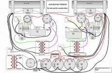
I am sketching this grounding plan for my 1st. amp. To be honest, I haven't read much about grounding practices, I have just followed my "intuition"
It all goes to the chassis at one point. Here is the diagram (ground wires in black)
¿Am I on the wrong way?
I am sketching this grounding plan for my 1st. amp. To be honest, I haven't read much about grounding practices, I have just followed my "intuition"
It all goes to the chassis at one point. Here is the diagram (ground wires in black)
¿Am I on the wrong way?
Attachments
P.D.
I've made this small Visio library to plan layouts fast and easy. I can send it to anyone interested.
I've made this small Visio library to plan layouts fast and easy. I can send it to anyone interested.
Why not create a solid ground rail around (in a U-shape) and connect the (short) wires to it. Easier to route, looks cleaner, and you then definitely have gotten yourself a "Star"-connection.
Hi,
Wouldn't that be a busground?
Cheers,😉
Easier to route, looks cleaner, and you then definitely have gotten yourself a "Star"-connection.
Wouldn't that be a busground?
Cheers,😉
plan
ola pingfloid
I'd be interested to have your library.
best regards
I've made this small Visio library to plan layouts fast and easy. I can send it to anyone interested.
ola pingfloid
I'd be interested to have your library.
best regards
- Status
- Not open for further replies.
- Home
- Amplifiers
- Tubes / Valves
- My first amp: Grounding