Hey guys! I'm (sort of) new here. I apparently made an account some years ago but didn't really use it. I'm an electrical engineering student and have been fascinated by tubes so I've decided to take the plunge and learn more about them by building an amp from scratch (not my first foray into messing with tubes though, I started with radio / guitar amp repairs and mods).
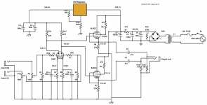
The amp I decided to build is an OTL headphone amp to drive my Sennheiser HD6XX. I started with the Darkvoice 336SE schematic as a starting point and heavily altered it. Part of the power supply is regulated (overkill?) and I wanted to try it with 6L6GC tubes in the output stage and kept the 6SN7 preamp. Not sure if the 6L6 is the best choice for this, I just chose it because I like that tube in guitar amps and have spares laying around.
Anyways, I would like some advice on how to improve what I've got. I am unsure of the bias point I have the tubes operating at. I tried my best to get them where I think they should be based on the datasheets, but alas this is my first project so I'm sure it can be improved.
Overall though, the amp does work (and it's LOUD AF heheh). And I'm mostly amazed by the sound I get from driving my headphones with it. The quality in the mids and bass is pretty good to my ear. The treble has pretty good clarity but can be quite piercing / harsh at times (depends on the song) and this is the main thing I'm looking at improving.
For the schematic I've included the filaments are powered directly from the 6.3VAC tap from the transformer, I left this wiring off so the schematic wouldn't get too messy. Also, the node voltages shown are the measured values relative to chassis ground.
Anyways, comments and tips / advice on improving my amp are appreciated!
Thank you.
EDIT: On the schematic the cathode resistor on the top 6L6 (R4) is supposed to be 2.2k ohms not 2.5k.
Attachments
Last edited:
If you don't need the gain remove C8 and C9 that will improve the distortion in the first stage a bit. Depending on your headphones C5 and C6 may need to be bigger to pass the bass I think they are 300R so 47u should be fine. Very nice.
Last edited:
I would be surprised if you were happy with the noise floor, is there hum or buzz with the 6xx cans and this design? A CRCRC filter with 100+ ohms per R leg and 220+uF for each C leg will get the hum down.
EL34s are far better suited for this situation than 6L6s are. The extra transconductance is quite helpful here.
EL34s are far better suited for this situation than 6L6s are. The extra transconductance is quite helpful here.
If you don't need the gain remove C8 and C9 that will improve the distortion in the first stage a bit. Depending on your headphones C5 and C6 may need to be bigger to pass the bass I think they are 300R so 47u should be fine. Very nice.
Yeah, the headphones have an impedance of 300 ohms. I thought I read somewhere that those bypass caps on the 6SN7 can reduce distortion? Could have been for transistors as that's what I've directly studied in my EE courses so far. Don't really need the gain, it was already bloody loud without the caps with the volume put turned most of the way down.
I would be surprised if you were happy with the noise floor, is there hum or buzz with the 6xx cans and this design? A CRCRC filter with 100+ ohms per R leg and 220+uF for each C leg will get the hum down.
EL34s are far better suited for this situation than 6L6s are. The extra transconductance is quite helpful here.
I can try EL34s. Is the high voltage for either of these tubes a bit on the low side or can EL34s and 6L6s operate well enough with the given voltage? And the noise floor is actually very low. Can't really hear much if any 60Hz hum and there is basically 0 ripple coming out of the regulator and close to 10mV of ripple off of the 3000uF cap.
One concern I have is the operating point I have the tubes at. I can plot the load lines and such but I'm not really sure what would constitute as a "good / ideal" load line plot and what not. Like how steep should the slope be for best quality. In terms of tube bias (at least for power tubes) I'm used to guitar amps where I bias them rather hot.
I'll probably end up trying out a few different tubes for fun as long as my power transformer can handle it (the HV tap is rated for 250mA and filament tap at 4.5A). One of my main objectives with this project is just to learn 🙂
Also, I noticed a typo on my schematic. The cathode resistor of the top 6L6 is also 2.2k ohms not 2.5k. Will update original post.'
Thanks for the replies so far

For load lines, you want your load line to cross the grid voltage lines in such a way that the load line is divided into even segments between the grid voltage lines.
If you are going to resistively load your cathode followers (which isn't a horrible choice), then it makes sense to have that 100V of bias at the grids to allow your cathode resistor to be a reasonably high value.
You have not indicated anything in your schematic, but you'll want to keep heater cathode insulation ratings in mind when messing around with designs like this.
Hi! Your choice is unusual but due to the schematic 6L6 seems to be ok.For humm noise reduction is better to use 5H choke instead R17.The output with C5/C6 ...try to use 220 micro in parallel with 1micro bipolar.Remove C8/C9 .For Sennheiser 600 HD i use a schematic with ECC88 and ECC99 in SRPP with splendid results.
Removing C5/C6 will reduce both distortion and gain. This is because without them when the grid goes up in voltage the current in the cathode increases. This increases the cathode voltage so there is now less voltage between grid and cathode - this reduces the current. Its a form of negative feedback.
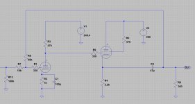
You could try a little feedback to reduce gain and distortion, like in the attached picture. Also try 330 ohm grid stoppers for both the 6SN7 and 6L6.
That would work but that with reduce the input impedance maybe bigger resistors. By the way simulation is a good way of checking your design.
Removing C5/C6 will reduce both distortion and gain. This is because without them when the grid goes up in voltage the current in the cathode increases. This increases the cathode voltage so there is now less voltage between grid and cathode - this reduces the current. Its a form of negative feedback.
Ah cool! Thanks for the explanation. I think where I got the idea was from a common emitter BJT type of amp. I know there's similarities with transistors and tubes so knowing a bit about them is helping the learning process here.
That would work but that with reduce the input impedance maybe bigger resistors. By the way simulation is a good way of checking your design.
And I did indeed simulate in LTspice using some tube models I found online. For some reason though, I could only get the 6L6 triode model to work out of the couple different 6L6 options the tube model pack I got. So I knew my design would at least function somewhat but what I'm hear for is the fine tuning.
Also the original output caps I was using were 100uF IC brand electrolytics and the 47uF I replaced them with are Jantzen polypropylene caps. Replace them did seem to smooth out the treble as well as improve bass definition. As of right now, I have no intentions of using this amp with lower impedance cans.
Oh and if anyone is curious, I measured the amp to have about 17dB of gain (without the bypass caps on the 6SN7 when I first built it, tubes biased a bit differently at that point too) when the output was loaded with a 300ohm load and driven with a 1kHz 0.1Vpk signal.
Nice circuit. I built a similar OTL based on Van Waarde's circuit. 6DJ8 and 6AS7. If your interested in mixing some transistors with your tubes you might try Constant Current Sources. Put the CCS where the AC signal "comes out of". Plate of the common cathode, cathode of the cathode follower. Here is an excellent reference on CCS. Sources 101: Audio Current Regulator Tests for High Performance - Full Article | audioXpress
Nice circuit. I built a similar OTL based on Van Waarde's circuit. 6DJ8 and 6AS7. If your interested in mixing some transistors with your tubes you might try Constant Current Sources. Put the CCS where the AC signal "comes out of". Plate of the common cathode, cathode of the cathode follower. Here is an excellent reference on CCS. Sources 101: Audio Current Regulator Tests for High Performance - Full Article | audioXpress
Definitely will have to check that out as I'm interested in doing that in the future. The first idea I had though was having a constant current source biased front end by using constant current sources and current sinks on the 6SN7 cathodes. I'm cool with mixing transistors with tubes as long as the tubes are doing the main work of that makes sense. I'm not what one would call a tube purist where it's "tube good transistor bad" type of thing heheh! I just think tubes look so cool!
One idea that recently popped into my head was to add some sort of balancing circuit to the output of the amp for balanced output to my headphones. Not sure how feasible that is with this type of amp and I'll have to wait till the end of the semester to look into it lol.
diyaudio have a link to a whole load of tube spice models. Just make sure you use the ltspice ones as there's a slight difference in the power operator (I think one uses ** and one ^) over pspice. This may be why some of your models don't work. You can check in the file and replace if wrong.
You can get a FFT plot from LTspice (set the min step size to 1us for best results). It will give you a guide as to what is generating distortion. It's only good down to about .1% due to math inaccuary
You can get a FFT plot from LTspice (set the min step size to 1us for best results). It will give you a guide as to what is generating distortion. It's only good down to about .1% due to math inaccuary
Last edited:
Also the original output caps I was using were 100uF IC brand electrolytics and the 47uF I replaced them with are Jantzen polypropylene caps. Replace them did seem to smooth out the treble as well as improve bass definition. As of right now, I have no intentions of using this amp with lower impedance cans.
As it is, with 47uF, at 20hz you will have about 6dB roll-off on 300ohms Sennheiser impedance.
You did see the sticky at the top of the page? There are a lot of crap tube models out there on the web.And I did indeed simulate in LTspice using some tube models I found online. For some reason though, I could only get the 6L6 triode model to work out of the couple different 6L6 options the tube model pack I got. So I knew my design would at least function somewhat but what I'm hear for is the fine tuning.
You did see the sticky at the top of the page? There are a lot of crap tube models out there on the web.
Yep. That's where I got the tube models from I was just having issues trying to get some of the 6L6 variants working.
Anyways guys, here's an update:
The amp has no problems with treble harshness now. I think the issue actually ended up being my HD6XXs and not the amp. These cans are fairly new and I probably didn't have many hours on them let alone any hours with an amp to properly drive them so I'm getting the feeling they weren't broken in. After using them for hours on my amp it seems like use made everything smooth out and the amp sounds (mostly) amazing now!
I've also changed the 6L6 tubes for JJ 6CA7s wired purely as triodes. This seemed to make the amp sound a little more airy / open in the top end.
There's only one little problem I have that I can't seem to figure out. One of the channels has a buzzing / hum in it that is puzzling me (thinking of making a new thread on this). I've tried swapping inputs around (it has 2 separate inputs 1 for each channel) and that does not switch which ear I'm hearing the buzzing in. Here's is the most puzzling part to me though, the buzzing is completely quiet with the volume all the way down, and it does increase / fade in as I turn the volume up. The volume knob has to be past a certain point to make the buzzing audible. BUT once I turn the volume knob far enough the buzzing goes away completely and with the volume on max there's no buzzing (some 60Hz hum but that doesn't really bother me). So basically the buzzing is only there in the upper mid range of the volume pots sweep!
Any thoughts on the issue?
- Home
- Amplifiers
- Tubes / Valves
- My first amp build... Tips / advice appreciated!