

...I'm speechless...
That really is an absolutely stunning piece of work!
I hope it sounds as good as it looks🙂
Many thanks for sharing it with us. It's inspirational
ciao
James
That really is an absolutely stunning piece of work!
I hope it sounds as good as it looks🙂
Many thanks for sharing it with us. It's inspirational
ciao
James
INCREDIBLE...
Hi,
Wooooow.....god allmighty....😱
That's frightening....most impressive indeed.
Sincere congratulations,😉
Hi,
Wooooow.....god allmighty....😱
That's frightening....most impressive indeed.
Sincere congratulations,😉
Amazing work 🙂
I've saved the pic of the inside of the amp in post #41
for future reference.
cheers 😉
I've saved the pic of the inside of the amp in post #41
for future reference.
cheers 😉
Hello Wardsweb;
That's one impressive amp - the craftsmanship is truly breathtaking!
All the best,
Morse
That's one impressive amp - the craftsmanship is truly breathtaking!
All the best,
Morse
I'm forced out of lurk mode by this simple seeming and perhaps elegant circuit. I don't grasp what's happening. I see only one filter cap. After the 15H choke are two ultrapath caps. Now I just finished one amazing ultrapath 6sn7 preamp so I thought I had at least a basic grasp of the concept. I was forced to use a massive power supply by the noise coupling effect of the cap. I assume the cathode caps remain in this 2a3 amp to assist in hum filtering but doesnt this defeat the purpose of the ultrapath as far as shortening the current path? I'm hoping that this concept really works. The workmanship is awsome. There are only two modest sized electrolytics in the entire amp. Come on Wardsweb, don't tease me. Whats really going on? Can you enlighten me as to the theory? How much hum? Does it sound anything like as good as it looks? I'm assuming that this is not a proof of concept amp because you put so much work in on cosmetics.
The ultrapath caps do act as filters by reducing AC potential between the plate and cathode of the output tube. They should be seen as filter caps. Notice the large values of inductance employed in the high voltage filtering of this amp. This allows for smaller filter caps of higher quality.
As regards the high voltage to ground AC filtering of the final cap stage, it is completed through the ultrapath and cathode bypass capacitors together. The final choke in the high voltage supply blocks audio signal from the output circuit from traversing the prior filter cap and the other channel. This is to compartmentalize the different stages of this circuit and avoid the "smearing" effect which can be a complaint when two caps of different characteristics are in parallel, such as an electrolytic bypassed with a polypropylene. It also improves stereo separation.
As regards the high voltage to ground AC filtering of the final cap stage, it is completed through the ultrapath and cathode bypass capacitors together. The final choke in the high voltage supply blocks audio signal from the output circuit from traversing the prior filter cap and the other channel. This is to compartmentalize the different stages of this circuit and avoid the "smearing" effect which can be a complaint when two caps of different characteristics are in parallel, such as an electrolytic bypassed with a polypropylene. It also improves stereo separation.
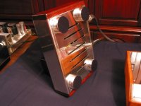
It's done
After a couple of final tweaks to get it dialed in, I got .33 ripple at the first filter cap and 2mV at the speaker terminals. Not the best amp money can buy but I'm real happy with my first endevor to the tube amp world.

After a couple of final tweaks to get it dialed in, I got .33 ripple at the first filter cap and 2mV at the speaker terminals. Not the best amp money can buy but I'm real happy with my first endevor to the tube amp world.
- Status
- Not open for further replies.
- Home
- Amplifiers
- Tubes / Valves
- My first amp - a direct coupled 2A3