Hi,
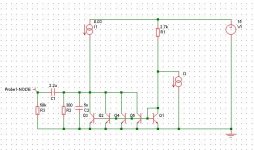
Here's what I did, based on my idea of the current mirors.
The output voltage is approx 2V RMS, and the Zout is 300R
I haven't build it yet. But the simulations give good results.
WARNING: this I/V won't work with a TDA1541, because the input voltage is fixed to 0.7V. If you want to use another DAC with this I/V, check that the voltage compliance is high enough.
The output has to be AC coupled, since there's a big offset on the 300R resistor. A 0.5W is recommended for this one.
Use your favorite PNP transistor for everything, but they all have to be the same. Matching them can also help.
The courrent source can be what you want, a BJT, some JFETs, an IC...
PS voltage should be between 12 and 17V
Attachments
I'm afraid the 1543 won't like to have its output tied to 0,7V.
The linear region is IIRC from 1,8V to Vcc-1,2V.
Your idea is nice but needs to be refined 😀
Cheers
Andrea
The linear region is IIRC from 1,8V to Vcc-1,2V.
Your idea is nice but needs to be refined 😀
Cheers
Andrea
Couldn't you just put a LED with 1.2 v in between the first transistor and the current input, assuming that I3 is in. Since it is current driven the varying voltage shouldn't matter that much, smaller than for a passive IV anyway.
Do not know the 1543 but since the voltage will be fixed by the led and transistor (releatively at least) couldn't you replace the resistor R1 with a current source.
Alternatively if you use a current source you could add emitter resistors on all transistors, reduces the matching problem i think.
Edit:
Saw now that the minimum linear voltage was 1,8 so use a 1,9v LED instead.
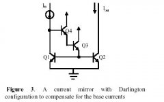
A current mirror like this might work better, tough I'd use a resistor to Vcc as load for the mirrored current, choosing its value so that it sets the collector of the 4 parallel Bjts at about half Vcc when there is digital silence.
Don't feel the need for R1 either, since the TDA has its internal current sources...
Cheers
Andrea
Don't feel the need for R1 either, since the TDA has its internal current sources...
Cheers
Andrea
Attachments
hjelm said:Andy:
This would fix the voltage at 3*Vbe?
Hopefully....
Bricolo said:You need R1, since you can't connect the TDA from Q1's base (in your schematic) to Vcc
The base should be connected to OUTL or OUTR, R1 might be helpful to keep the bjts polarized when the signal current has its maximum value (and so the current sourced by the TDA is at its minimum); this bias current can be however sourced from the TDA choosing Rref so that Vbias exceeds the full scale current of the DAC by at least the current needed to keep the mirror biased.
Cheers
Andrea
Andy, yous curent miror works. The good thing is that the input voltage is now 1.8V
The "bad" thing is that now, the TDA sees much more AC voltage at its output.
I'll try cascoding Q1, but I'm not sure it will work. Since Q1 is only a diode, cascoding a diode ...
The "bad" thing is that now, the TDA sees much more AC voltage at its output.
I'll try cascoding Q1, but I'm not sure it will work. Since Q1 is only a diode, cascoding a diode ...
Bricolo said:Andy, yous curent miror works. The good thing is that the input voltage is now 1.8V
The "bad" thing is that now, the TDA sees much more AC voltage at its output.
Why "much more"?
Surely no more than with passive I/V 😀 ...
Cheers
Andrea
- Status
- Not open for further replies.
- Home
- Source & Line
- Digital Source
- My experimental I/V stage for TDA1543