Not wanting to get in the way of the development of the new ESS Dac, and following Russ suggestion, I'll move my progress works on my ESS Sabre Buffalo DAC on this thread.
I started with interconnect diagram of the different Twisted Pear modules on how to build the Buffalo. Here they Counterpoint I/V converter version:
I started with interconnect diagram of the different Twisted Pear modules on how to build the Buffalo. Here they Counterpoint I/V converter version:
Attachments
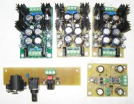
Just completed most of the support PCB for my Buffalo. One LCDPS for the digital supplies, two LCBPS (my own PCB and parts choice) for the upcoming CounterPoint ver2, the digital input PCB with AES/EBU, True 75 ohms BNC and optical SPDIF using the TORX142L (192Khz speed support). The RCA is not mounted because I'll use the USB input card for the forth input into the CS8416 MUX.
There is also the small Simple Reg PCB for the Buffalo analog reference modification. The MUX is all assembled as well as the Buffalo. I just need to complete the USB card and wait for the Counterpoints.
There is also the small Simple Reg PCB for the Buffalo analog reference modification. The MUX is all assembled as well as the Buffalo. I just need to complete the USB card and wait for the Counterpoints.
Attachments
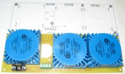
I made also a Transfo PCB to receive all three power transformer, one for the digital section, and one for each futur Conterpoint I/V converter (dual mono).
The board has these features:
External Power switch pads, option to turn on the digital section separate or together with the analog section (to keep the analaog section turn on all the time, if desired), fuse holder. The IEC320 AC socket will come from the bottom of the DAC enclosure, ala ML38 style, so AC won't be near the DAC electronic, but close to the front.
The Main Power switch will be under the case, near the front.
The front panel will have a secondary power switch for the digital section only, inputs selector switch, and a few leds (power-On, Lock, etc...)
Attachments
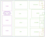
I'll put the Buffalo into a nice enclosure from www.hifi2000.it that I got from an other project. It is the Galaxy Serie, model 248. I have a nicely machined aluminum front panel to go with it. I used AutoCAD and made sure that all PCB will fit inside. I used this tool also to design the size the transfo PCB. Here the future enclosure PCB location.
Digital inputs, including USB will be in the middle of the rear panel. Single ended and balanced outputs will be at each sides. AC will come from under, near the front.
Digital inputs, including USB will be in the middle of the rear panel. Single ended and balanced outputs will be at each sides. AC will come from under, near the front.
Attachments
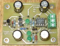
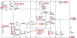
Algar_emi said:Here my version of Simple Reg PCB.
Very nice. Are you planning on also driving the clock with this supply?
Nice Thread. I really appreciate your contribution to the project!
Especially your wiring documents. very well done and very helpful.
Cheers!
Russ
Especially your wiring documents. very well done and very helpful.
Cheers!
Russ
- Status
- Not open for further replies.
- Home
- Source & Line
- Digital Line Level
- My ESS Sabre Buffalo DAC