Three wire and yes its connected and tried with a disconnect, same.Do you have a two wire or three wire power cord?
If three wires, is the chassis grounded?
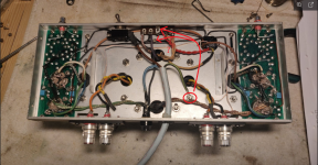
I now I have restored a couple before without no problem, i insert pictures.Please post a PICTURE of the inside of the amp. the Hum is 99.9% due to a ground loop (somewhere). This is a very established old-school design that does NOT hum.

When I renovated the first ST 35 I learned that the rca input must be grounded to the chassis and it is also like this.
I have thought a lot about how it was when I bought the original EL 84 was replaced with others and the 7247 is Dynaco. I'm beginning to suspect that what OldHector writes about double voltage, if it is, I understand that the EL 84s have been replaced and then the 7247 has also broken, then it's just a matter of replacing it.
Petertub I live in Skåne.
i pass skåne from time to time ( sjöbo) and may make a detour to pick it up. Mess me if you need support.
i also have all needed tubes, new from JJ .
i also have all needed tubes, new from JJ .
you sure that the hum is 50 hz... this type of hum coming from filimant or is it the effect of the trans electric field? Is there another way?
Since this is an old production, there is no need to DC for ff . The cathode of the power tubes is connected to the filaments. This is a for 50hz hum .
Since this is an old production, there is no need to DC for ff . The cathode of the power tubes is connected to the filaments. This is a for 50hz hum .
50Hz hum (from 50Hz mains) suggests ground loop to me. I see lots of potential ground loops on this chassis. Thanks for posting the pictures...
For a potential quick fix, move the ground connect on the chassis to the screw that holds the ground connect on this tab board instead (like I indicate in the attached picture... or maybe the screw under it which is on the chassis...
For a potential quick fix, move the ground connect on the chassis to the screw that holds the ground connect on this tab board instead (like I indicate in the attached picture... or maybe the screw under it which is on the chassis...
Attachments
Last edited:
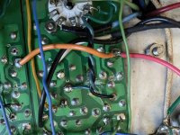
I modified my SCA-35 with repro Stereo 35 boards and the EFB circuit. I found that with the EFB, the driver tube was a little more susceptible to picking up heater hum. I'm not sure why that would be, but if your boards approximately follow the original layout like mine do, there's a long run on one of the heater traces. I cut those traces short, then ran a tightly twisted pair from the near EL84 to the driver/phase splitter tube. Green and black twisted pair in the picture. This fixed the problem.
Attachments
It is the safety ground and should not be connected to main ground just far away from it.50Hz hum (from 50Hz mains) suggests ground loop to me. I see lots of potential ground loops on this chassis. Thanks for posting the pictures...
For a potential quick fix, move the ground connect on the chassis to the screw that holds the ground connect on this tab board instead (like I indicate in the attached picture... or maybe the screw under it which is on the chassis...
I will take a look at that, thanks.I modified my SCA-35 with repro Stereo 35 boards and the EFB circuit. I found that with the EFB, the driver tube was a little more susceptible to picking up heater hum. I'm not sure why that would be, but if your boards approximately follow the original layout like mine do, there's a long run on one of the heater traces. I cut those traces short, then ran a tightly twisted pair from the near EL84 to the driver/phase splitter tube. Green and black twisted pair in the picture. This fixed the problem.
Nonsense, moving the safety ground closer to what appears to be the main ground point won't hurt. If it changes the hum level then it is most certainly a ground loop!It is the safety ground and should not be connected to main ground just far away from it.
Looking at his boards (right and left) it also seems that they might grounded to more than one point (it's hard to tell for certain though). It could also very well be that the grounding of the 'Gillespie' fixed bias board is the culprit. Maybe it is grounded by wire, as well as directly to the chassis, or the bell of a transformer, etc.. This appears to be a tight build so could easily happen.
Ever have the stand-off touch the ground of the circuit board (as well as the chassis), and also have a 'proper' ground wire connection from the circuit board? That becomes an instant ground-loop. There are seriously many potential sources of ground-loops.
Look at the picture hooman posted. This is what the st-35 normally look like - lots of space and simple layout. I know from experience that the version of this amp doesn't hum.
Here is a very useful (yet tedious) approach: Pull everything off the chassis and breadboard it. I mean Everything. When you breadboard it use a single ground point or thick copper rail for the main ground. It seriously shouldn't hum then. As usual take lots of precautions and ensure the iron won't fall off your very solid board. This will also allow you to scope everything nicely too btw. Oh and use some cheapo testing speakers too of course (nothing expensive).
Many times I had convinced myself that there was no ground loop, and that the hum had to be coming from something else. Then, after lots of experimenting - many wasted hours - I breadboarded the circuit, and in doing so discovered that it was indeed a ground loop...
Last edited:
soulmerchant from experience expensively bought such, I have learned that safety ground should not be near the chassis, signal ground and voltage ground which I prefer to collect in the same place.Hooman's st35 is one of the better examples how it should look. Then we must consider that most of the people who built these had zero idea what they were doing, even their English was non-existent.
I have done every possible variation to see if there is a ground loop but there are two tests left that I will try before I take it apart again.
I would try making up a source of 6.3V DC heating power, and apply that on a channel in place of the AC. If I'm remembering right, that's how I found the issue in my build. No need to tear the whole thing apart. Checking for duplicate ground paths is of course also a good idea, but I think it would give you 100hz buzz rather than 50hz hum.
I see the safety ground already mounted on the chassis - also, I did not mean to permanently move it (I would not do that either). But let's drop this because it's not moving things forward. 🙂soulmerchant from experience expensively bought such, I have learned that safety ground should not be near the chassis, signal ground and voltage ground which I prefer to collect in the same place.
If it were me, I would remove everything from the chassis and set it up on a nice firm piece of plywood on my bench. And I do mean everything off the chassis. Remove everything in "As if you were going to send the chassis out for sand-blasting and a new powder coat".
Then I would wire the amplifier up as I had described above, with a single ground point (or thick copper wire) and zero ground loops. I suspect the culprit is the 'fixed bias board'. Like I noted, it is very easy to inadvertently get a 2nd ground connection off such things.
petertub: I believe you. The cause may be a combination of factors. But I'm also speaking from experience specific what happened with my amp. Several things may be different:
There aren't many likely causes for 50hz hum in the amp, 100hz buzz would be more likely in various scenarios. Plus testing/fixing possible heater hum induced into the 7247 is one of the easiest things to try, and a tight twist to the tube pins is more theoretically correct anyway.
- I'm using reproduction boards with fatter traces closer together.
- My EFB is the published circuit, but not on a PCB
- Different tube construction may be more/less susceptible to heater hum
- my build is in a SCA-35 chassis so the layout is different
There aren't many likely causes for 50hz hum in the amp, 100hz buzz would be more likely in various scenarios. Plus testing/fixing possible heater hum induced into the 7247 is one of the easiest things to try, and a tight twist to the tube pins is more theoretically correct anyway.
As a test, feeding filament with DC as "jgf" did is a definitive way of excluding large portions of the hum source.
This is what most of trouble-shooting is about : reducing the problem area by eliminating possible (and impossible)
sources. This avoids needless replacements of components.
With hum there is also of value to note the exact level and frequency spectrum, this will hint how close you are
to the problem.
Now I have eliminated as much as possible and it is exactly the same result but the difference is that now I hear music, But the higher the pulses get, the more distorted the music get eventually becomes so loud that it clip without raising the volume from half of what the portable CD will do.
I will try with separate DC voltage on the filament to rule that out.
I'm starting to think more and more that the mains transformer can be broken because one 115V winding (115 + 115 = 240V) has been pinched between the transformer and the metal chassis (chassie ground), but then I think it's strange because it doesn't have any strange readings when checking all the voltages.
But whatever it is, I'm positive because I learn something.
Last edited:
- Home
- Amplifiers
- Tubes / Valves
- My Dynaco ST 35