
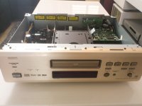
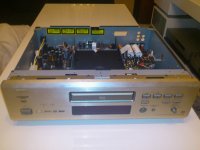
The process of my mod
On the DENON DVD 2900
audio circuit
I removed the muting transistor
TR231
TR232
I replaced the capacitors
C220
C221
In the capacitor
RUBYCON - 16ZLH220MEFC6.3X11 - CAPACITOR, 220UF, 16V
I replaced the capacitor
C 234
To
RUBYCON - 35ZLH470MEFC10X16 - CAPACITOR, 470UF, 35V
I changed the film capacitors
C371-C374
To
VISHAY ROEDERSTEIN - KP1830147631 - CAP, FILM, 470PF, 1%, 630V, RADIAL
I removed all capacitors
C355
C356
C357
C358
C365
C366
C367
C368
And replaced by two capacitors 10UF 250V
Of
VISHAY ROEDERSTEIN - MKT1813610255GQ - CAP, FILM, 10UF, 10%, 250V, AXIAL
Minus of capacitor C357
Plus a capacitor to C360
Minus of capacitor C355
Plus a capacitor to C359
the 2 op amps op275 ( ic216 . ic217 )
I replace next week to op amp -AD826
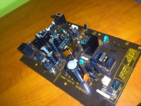
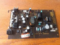
The mode power supply
Four diodes
D901-D904
I changed to
VISHAY SEMICONDUCTOR - VS-ETX0806FP-M3 - DIODE, HFAST RECT, 600V, 8A, TO220FP
the capacitor c905 - 47uf 400v
i changed to
RUBYCON - 450CXW220MEFC18X50 - CAPACITOR, 220UF, 450V, 20%, 18X50MM
the capacitor c914 2200uf 6.3v
i changed to
RUBYCON - 25ZLH2200MEFC12.5X30 - CAPACITOR, 2200UF, 25V
the capacitor c915. c917 -1200UF 16V
i changed to
RUBYCON - 35ZLH1200MEFC12.5X25 - CAPACITOR, 1200UF, 35V
the capacitor c950 220uf 16v
i changed to
RUBYCON - 16ZLH220MEFC6.3X11 - CAPACITOR, 220UF, 16V
the capacitor c958 . c959 220uf 16v
i changed to
RUBYCON - 35ZLH470MEFC10X16 - CAPACITOR, 470UF, 35V
the capacitor c928 470uf 6.3v
i changed to
RUBYCON - 35ZLH470MEFC10X16 - CAPACITOR, 470UF, 35V
To be continued 😉
On the DENON DVD 2900
audio circuit
I removed the muting transistor
TR231
TR232
I replaced the capacitors
C220
C221
In the capacitor
RUBYCON - 16ZLH220MEFC6.3X11 - CAPACITOR, 220UF, 16V
I replaced the capacitor
C 234
To
RUBYCON - 35ZLH470MEFC10X16 - CAPACITOR, 470UF, 35V
I changed the film capacitors
C371-C374
To
VISHAY ROEDERSTEIN - KP1830147631 - CAP, FILM, 470PF, 1%, 630V, RADIAL
I removed all capacitors
C355
C356
C357
C358
C365
C366
C367
C368
And replaced by two capacitors 10UF 250V
Of
VISHAY ROEDERSTEIN - MKT1813610255GQ - CAP, FILM, 10UF, 10%, 250V, AXIAL
Minus of capacitor C357
Plus a capacitor to C360
Minus of capacitor C355
Plus a capacitor to C359
the 2 op amps op275 ( ic216 . ic217 )
I replace next week to op amp -AD826
The mode power supply
Four diodes
D901-D904
I changed to
VISHAY SEMICONDUCTOR - VS-ETX0806FP-M3 - DIODE, HFAST RECT, 600V, 8A, TO220FP
the capacitor c905 - 47uf 400v
i changed to
RUBYCON - 450CXW220MEFC18X50 - CAPACITOR, 220UF, 450V, 20%, 18X50MM
the capacitor c914 2200uf 6.3v
i changed to
RUBYCON - 25ZLH2200MEFC12.5X30 - CAPACITOR, 2200UF, 25V
the capacitor c915. c917 -1200UF 16V
i changed to
RUBYCON - 35ZLH1200MEFC12.5X25 - CAPACITOR, 1200UF, 35V
the capacitor c950 220uf 16v
i changed to
RUBYCON - 16ZLH220MEFC6.3X11 - CAPACITOR, 220UF, 16V
the capacitor c958 . c959 220uf 16v
i changed to
RUBYCON - 35ZLH470MEFC10X16 - CAPACITOR, 470UF, 35V
the capacitor c928 470uf 6.3v
i changed to
RUBYCON - 35ZLH470MEFC10X16 - CAPACITOR, 470UF, 35V
To be continued 😉
Last edited:
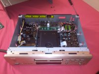
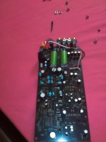
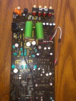
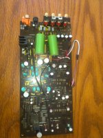
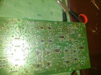
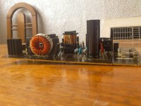
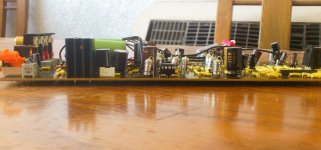
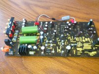
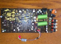
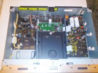
More improvement that I made to the audio circuit DENON DVD 2900
Today I made a point to point wiring to the audio circuit
I used wire cable NEOTECH 3001
(Yellow in photo) 😉
Today I made a point to point wiring to the audio circuit
I used wire cable NEOTECH 3001
(Yellow in photo) 😉
Attachments
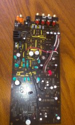
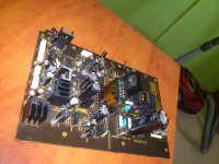
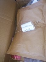
Today I Received all the parts I ordered to continue the project
On the 2900
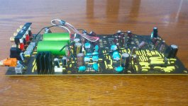
I replaced on the power supply all capacitors to RUBYCON ZLK
And the coil L950 from 4.7UH
to
BOURNS - 2318-V-RC 330UH
I replaced on the audio circuit the OP AMP -OP275
IC216
IC217
To AD826
and All blue film capacitors capacitors replaced to LCR
4 legs of the DENON
i Replaced to the feet of
BDR
On the 2900
I replaced on the power supply all capacitors to RUBYCON ZLK
And the coil L950 from 4.7UH
to
BOURNS - 2318-V-RC 330UH
I replaced on the audio circuit the OP AMP -OP275
IC216
IC217
To AD826
and All blue film capacitors capacitors replaced to LCR
4 legs of the DENON
i Replaced to the feet of
BDR
Attachments
Last edited:
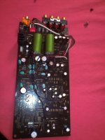
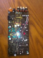
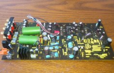
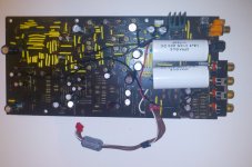
I changed the I/V OP AMP
NJM2068
to AD4562
In addition i add l film capacitors between
V +
To
V-
on each op amp (leg 4 to leg 8 )
i used a capacitor of VISHAY MKP1830
470PF
(At first I used a value of 10NF but it affected by the sound tone is soft)
Next Step replacing all resistors in the audio circuit
VISHAY DALE 1 to%
And all the ceramic capacitors
to film capacitor of
VISHAY MKP1837 - 0.1 UF
Attachments
Really looking forward to your listening impressions. I have a Denon 2900 that has been retired to my man cave 2 channel tube audio setup. It's already a fantastic sounding player but the gear it's hooked up would take advantage of every inch of quality I could squeeze from this thing.
I finished the project on the DENON 2900
I changed the OP AMP filtering
IC 317
IC 318
BA15218
To
OPA1662
The change is much more fast response
The sound is much more dynamic.
After that I replaced all the Carbon resistors
to Film resistors
of
VISHAY DALE 1%
I replaced the ceramic capacitors
C316
C317
C318
C318
film capacitors to LCR- FILM CAPACITOR - 2200PF
The final test that I promised
I changed the
Output capacitors
From
VISHAY 1813MKT-10UF
To
VISHAY 735P MKP-10UF
The 735P
Produce sound is quite different in 1813
The sound produced in 1813 more
With Treble
And clean
The 735P
Give a completely different sound
More fully
The sound got more energy especially rock music
One last thing I added
Cable that provides power to the audio circuit I added a
FERRITE CORE FILTER
of
FAIR-RITE - 0431164951 - 4.9mm
Material Grade 31 --- 1mhz-300mhz
Attachments


Last edited:
well I'm excited to find there is still someone out there modifying this machine. I've just bought one (for the embarrassingly low price of £26) and am keen to get started on some of the long-standing mods. Does anyone have the schematic or a board layout diagram I could study to find my way around inside when I first open it up?
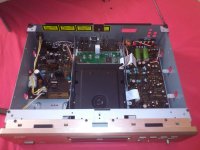
schematics of legible resolution needed
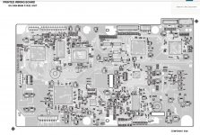
I have a pdf of the service manual, which is also online here at present:
Service Manual DVD2900
however the resolution of the circuit layout images is just too poor to read the component numbers. I attach an example.
If anyone can supply a higher resolution version of these diagrams it would be really helpful!
Attachments
-
hfe_denon_dvd-2900_service.part07.zip781.7 KB · Views: 85
-
hfe_denon_dvd-2900_service.part08.zip781.7 KB · Views: 85
-
hfe_denon_dvd-2900_service.part09.zip781.7 KB · Views: 87
-
hfe_denon_dvd-2900_service.part10.zip781.7 KB · Views: 88
-
hfe_denon_dvd-2900_service.part06.zip781.7 KB · Views: 82
-
hfe_denon_dvd-2900_service.part05.zip781.6 KB · Views: 105
-
hfe_denon_dvd-2900_service.part04.zip781.7 KB · Views: 90
-
hfe_denon_dvd-2900_service.part03.zip781.7 KB · Views: 85
-
hfe_denon_dvd-2900_service.part02.zip781.7 KB · Views: 70
-
hfe_denon_dvd-2900_service.part01.zip781.6 KB · Views: 104
Unzip the 15 file
And Enjoy
And Enjoy
Attachments
Last edited:
Thank you for those, can you give me any advice about opening them? If I unzip one I get a compressed .rar file. If I uncompress that I get an empty folder...
Thank you for those, can you give me any advice about opening them? If I unzip one I get a compressed .rar file. If I uncompress that I get an empty folder...
Put the 15 files in one folder unzip
Then RAR file
Unzip
I Can not upload large files on this site
So I had to deploy to 15 files to upload
Put the 15 files in one folder unzip
Then RAR file
Unzip
I Can not upload large files on this site
So I had to deploy to 15 files to upload
Brilliant, works perfectly. Sorry, that is my first experience of multi-part rar files.
For anyone else who is as ignorant as me: you have to unzip all fifteen parts so you have 15 .rar files in one folder, then set your favourite unrar program working on part01, and it will pick up the rest itself and reconstruct the original: you get the full Denon pdf out.
Now I can start work!
Good luck 🙂
How does the machine sound now, Dazzz?
Do you have the problem with clicking that has been described by several people on the old DVD-2900 modification threads?
Did you reassemble the machine and listen at any stage during this process? If so, what gave the biggest change?
Do you have the problem with clicking that has been described by several people on the old DVD-2900 modification threads?
Did you reassemble the machine and listen at any stage during this process? If so, what gave the biggest change?
- Home
- Source & Line
- Digital Source
- my dvd denon 2900 mod dazzz style :)