Hi, whilst I have scoured this forum for info in the past I think I have made one post to date since 2006! Maybe this will make up for the lack of input till now.
I designed and built these a few years ago, and now am approaching that time of year when I get some time to play with these things (Christmas holidays) thought I'd post and share what I've done to date well in advance and ask for some input / feedback / criticisms etc I may be able to use when the time comes.
Bit of history :
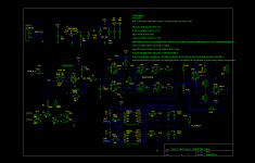
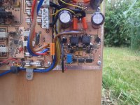
Whilst researching FET's I stumbled across the SI7322, I was somewhat sceptical of the specifications and decided to build what was intended to be a simple lash-up to see what they could do. No particular effort was put into the design in regards to audio quality, however due to their tiny size I had to make a fairly decent PCB. Inspired by the Sorensen project I went for the self oscillating technique, but opted for a single supply rail / full bridge configuration using only N channel FETs. I found a cheap easy to use FET driver (LM5100). Having built a channel it initially ran at about 1.6MHz, too fast! and got quite hot with excessive switching, adding R1 and C4 in the schematic slowed it down to around 500kHz. The rise times of the comparator output are fairly sensitive to temperature, with the pull-up resistors fighting only stray capacitance. Some small capacitors could improve this behaviour, but shoot through seems to stay within safe limits with the 2k2 resistors.
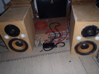
Having built a single channel and done a few tweaks/tests not expecting much I shocked myself with both how well this thing performed and how good it seems to sound, so I built a another to make a stereo pair!
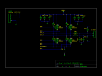
Originally I was using air core inductors but eventually after experiments with various configurations I settled on some 22uH items from Wurth which were recommended somewhere on this forum. The Air core inductor provided the most efficient performance at low power levels. I am not sure if it can be called quiescent current on a class D - but the idle running current is lowest with the air cores and substantially greater with other inductors. The Wurth proved the best non air-core inductor I could find, with idle current of about 80mA at 50 volts (from memory). The greatly reduced EMI of the enclosed inductors reduced audible switching noise to almost nothing even with ear right up-to the tweeter.
Unfortunately the wurth inductors having a saturation current of about 5 amps do limit the peak power to about 200Watts per channel, but as my power supply currently can barely achieve this its not to much of a problem. I have recently seen a version with 11amp saturation current which I think I shall try.
I can run these things close to clipping (200Watt peaks) indefinitely with no assistance in cooling, with the bigger inductors and maybe a fan I should be able to get a fair amount more.
I am using these as part of an active speaker system, so am not too bothered about the UCD approach, my feedback paths taken before the output filters.
They operate from a 10V supply for the signal and fet drive, and another voltage level that can be anywhere up-to about 80volts. Generally runs from up-to nearly 60 volts worth of NiMH batteries, or a 50V supply from a Toroid.
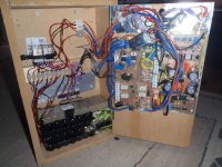
I generate a regulated +/- 15V supply and have an MCU doing some monitoring of the rails and controlling start-up/shut-down/speaker isolation relays etc on another PCB. There is a pre-amp housed in a separate unit away from the main speaker cabinet to avoid picking up switching noise and to make it easier to control volume (although the volume pot recently broke and is removed in the photo) if used in car etc. The +/- 15V regulated supplies and and audio feeds are fed to / from this unit via multi-core screened cable.
In a revised version I intend to implement balanced line inputs and drive the opamp and comparator from +/- 15Volts for better slew rate - and thus eliminate the 5 volt regulator acting as a (somewhat noisy) reference.
This will hopefully eliminate the small amount of remaining switching noise.
Looking forward to comments / suggestions.


I designed and built these a few years ago, and now am approaching that time of year when I get some time to play with these things (Christmas holidays) thought I'd post and share what I've done to date well in advance and ask for some input / feedback / criticisms etc I may be able to use when the time comes.
Bit of history :
Whilst researching FET's I stumbled across the SI7322, I was somewhat sceptical of the specifications and decided to build what was intended to be a simple lash-up to see what they could do. No particular effort was put into the design in regards to audio quality, however due to their tiny size I had to make a fairly decent PCB. Inspired by the Sorensen project I went for the self oscillating technique, but opted for a single supply rail / full bridge configuration using only N channel FETs. I found a cheap easy to use FET driver (LM5100). Having built a channel it initially ran at about 1.6MHz, too fast! and got quite hot with excessive switching, adding R1 and C4 in the schematic slowed it down to around 500kHz. The rise times of the comparator output are fairly sensitive to temperature, with the pull-up resistors fighting only stray capacitance. Some small capacitors could improve this behaviour, but shoot through seems to stay within safe limits with the 2k2 resistors.
Having built a single channel and done a few tweaks/tests not expecting much I shocked myself with both how well this thing performed and how good it seems to sound, so I built a another to make a stereo pair!
Originally I was using air core inductors but eventually after experiments with various configurations I settled on some 22uH items from Wurth which were recommended somewhere on this forum. The Air core inductor provided the most efficient performance at low power levels. I am not sure if it can be called quiescent current on a class D - but the idle running current is lowest with the air cores and substantially greater with other inductors. The Wurth proved the best non air-core inductor I could find, with idle current of about 80mA at 50 volts (from memory). The greatly reduced EMI of the enclosed inductors reduced audible switching noise to almost nothing even with ear right up-to the tweeter.
Unfortunately the wurth inductors having a saturation current of about 5 amps do limit the peak power to about 200Watts per channel, but as my power supply currently can barely achieve this its not to much of a problem. I have recently seen a version with 11amp saturation current which I think I shall try.
I can run these things close to clipping (200Watt peaks) indefinitely with no assistance in cooling, with the bigger inductors and maybe a fan I should be able to get a fair amount more.
I am using these as part of an active speaker system, so am not too bothered about the UCD approach, my feedback paths taken before the output filters.
They operate from a 10V supply for the signal and fet drive, and another voltage level that can be anywhere up-to about 80volts. Generally runs from up-to nearly 60 volts worth of NiMH batteries, or a 50V supply from a Toroid.
I generate a regulated +/- 15V supply and have an MCU doing some monitoring of the rails and controlling start-up/shut-down/speaker isolation relays etc on another PCB. There is a pre-amp housed in a separate unit away from the main speaker cabinet to avoid picking up switching noise and to make it easier to control volume (although the volume pot recently broke and is removed in the photo) if used in car etc. The +/- 15V regulated supplies and and audio feeds are fed to / from this unit via multi-core screened cable.
In a revised version I intend to implement balanced line inputs and drive the opamp and comparator from +/- 15Volts for better slew rate - and thus eliminate the 5 volt regulator acting as a (somewhat noisy) reference.
This will hopefully eliminate the small amount of remaining switching noise.
Looking forward to comments / suggestions.
Attachments
Impressive work. The materials used in off-the-shelf toroid inductors are intended for SMPS filter or output inductors, not for class D. Permeability is higher to reduce turn count and copper loss at the expense of higher core loss. Try micrometals -2 material (or similar) toroids, these are low permeability and work the opposite, low core loss at the expense of more turns. Try to choose a core size meeting your saturation current requirements and allowing a single layer winding (to reduce capacitance). Use a not too thick wire gauge, just enough for 1/3 or 1/2 power.
Hi Eva, thankyou for responding.
The inductor/magnetics is probably the part i know least about! I have tried on various occasions to understand them but the shere number of parameters and configurations is somewhat baffeling.
I have managed to build various dc-dc converters in the past (including one that does about 300 watts 12-60 volts, and a modded pc psu to output +/- 35v), re-using parts from old pc psu's (dismantling and rewinding e cores etc and experimenting with rc timing of the tl494 or similar) but i have to admit i get them to work more by experimentation and luck than by calculation, i can work out the ratios of input to output windings easily enough and know basic principles about number and arrangemnt of turns but that is about it.
My usual suppliers in the uk (rs/farnell) do not seem to carry these micometals parts but i will try to source some.
Osilly scope or not.. IMO that looks like a plate of Spaghetti and with more chips than a cheap buy of fish 'n chips. 🙂
What ?? have you cobbled together there?
Especially liking the dozens of obsolete round cells.. as that final touch of well conceived elegance.
Hope it works better than it looks 🙂
What ?? have you cobbled together there?
Especially liking the dozens of obsolete round cells.. as that final touch of well conceived elegance.
Hope it works better than it looks 🙂
. Use a not too thick wire gauge, just enough for 1/3 or 1/2 power.
Could you please explain why the wire should not cover 100% of the output current?
Osilly scope or not.. IMO that looks like a plate of Spaghetti and with more chips than a cheap buy of fish 'n chips. 🙂
What ?? have you cobbled together there?
Especially liking the dozens of obsolete round cells.. as that final touch of well conceived elegance.
Hope it works better than it looks 🙂
Hehe, mostly due to using what i had to hand and reusing bits of previous projects. Four of the battery packs are wired via relays so that they are in series providing upto 60 volt when no mains in available. When powered by mains (toroid and small smps in the back of the other cabinet) the relays configure the packs to each be charged via constant current (lm317s on the ali plate).
If i do get around to making a newer version i will build both channels and the controll system on a single pcb.
The main issue with it at present is the use of lm317 to generate 10v from a 12 volt battery. The drop out voltage is nearly 3 volts so the system will currently only run for about 5 hours, the time it takes for the battery to drain from its full charge voltage to around about 12.8 volts - the control/monitor board prevents it from trying to run when the 10 volt is outside limits.
A 10 volt fixed ldo regulator could be used sort this out.
Could you please explain why the wire should not cover 100% of the output current?
I would like confirmation of this but i suspect its due the the nature of music signals (peak power vs average / RMS power) and the saturation current vs copper power handling. the saturation current of the inductor must not be exceeded by the peaks, yet the copper can handle peaks and should be rated to match the avaerage power.
The main issue with it at present is the use of lm317 to generate 10v from a 12 volt battery. The drop out voltage is nearly 3 volts so the system will currently only run for about 5 hours, the time it takes for the battery to drain from its full charge voltage to around about 12.8 volts - the control/monitor board prevents it from trying to run when the 10 volt is outside limits.
A 10 volt fixed ldo regulator could be used sort this out.
The LT3022 isn't a fixed voltage LDO, but it can be set for 10V and has a lower dropout (145mV typical) than a lot of fixed LDOs.
The LT3022 isn't a fixed voltage LDO, but it can be set for 10V and has a lower dropout (145mV typical) than a lot of fixed LDOs.
That's an impressive chip! For the my current system I think I'll go with a simple 3 pin device, but I'll bear that in mind for future PCB builds.

- Status
- Not open for further replies.
- Home
- Amplifiers
- Class D
- My DIY class D