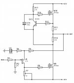
However, I also tried the output stage with an Aleph source (or similar), but ended up with the schematic shown, which is something between the Aleph source and the "Amp Camp". But the strange thing is: The distortion is much lower (says the simulator) for this modified amplifier shown.
So my question is: Have someone tried a similar configuration and has an idea of how it sounds?
So my question is: Have someone tried a similar configuration and has an idea of how it sounds?
Attachments
The idle current for the input JFET is about 4.5 mA and about 1.1 A for the MOSFETs. As can be seen from the attached files deskamp1.txt and deskamp2.txt, the distortion drops from 0.3% to 0.02%.
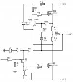
Try this on the deskamp1 sim. Change R10 to 0.82 ohm. Change R11 to 0.15 ohm. Add a 1K (or thereabout to maintain Iq) resisitor from base to emitter on Q13. That should drop distortion significantly. Feeling lucky? Change M9 and M16 to smaller devices like IRF520.
It's not hard to drop the measured distortion of the ACA when you change the gain/feedback ratio. Nelson likes the gain reduction to be around 10dB because that keeps the distortion low order. I find that when I listen to a CD through the ACA (even with feedback disconnected), I want to listen to another one instead of do something else.
It's not hard to drop the measured distortion of the ACA when you change the gain/feedback ratio. Nelson likes the gain reduction to be around 10dB because that keeps the distortion low order. I find that when I listen to a CD through the ACA (even with feedback disconnected), I want to listen to another one instead of do something else.
Thank you for your advice! I have tried it on the simulator, and you are perfectly right. I used an extra resistor of 1.5k and got the results attached in deskamp3.txt.
To be sure, I checked my first sim run (deskamp1.txt) and found that the capacitor C14 was too low. The right sim result is attached in deskami_rev.txt.
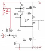
So, what is the conclusion? I think I will stick to deskamp1, but maybe I should add your extra resistor and try with different values of R10 and R11 when coming to real life. Simulations can be fun, but you can't listen to them....
To be sure, I checked my first sim run (deskamp1.txt) and found that the capacitor C14 was too low. The right sim result is attached in deskami_rev.txt.
So, what is the conclusion? I think I will stick to deskamp1, but maybe I should add your extra resistor and try with different values of R10 and R11 when coming to real life. Simulations can be fun, but you can't listen to them....
Attachments
deskamp 1 build
I like your design and will give a try. 2SK170 will be the jfet and c14 will be 2200uf low esr. also will add the resistor between gate and emitter probably 1.21k. hold up will be R10&R11 increase as values in 2-3 watt resistors seem to be hard to find these days. I have at present .33 ohm .22ohm and .47ohm. I could use parallel and series grouping to gain proposed values but that takes up so much space. Also hav 24vct 10 amp tranny from MPJA.
Any further development clues would be appreciated.
further on build
also (trying to use what's here) will use 5k multi turn trimmer set iniiately at
2k. Question why 1meg at input??
also (trying to use what's here) will use 5k multi turn trimmer set iniiately at
2k. Question why 1meg at input??
No it won't (unless you wanto to turn the whole circuit upside down) beacuse the k170 is a N-channel JFET (J175 is a P-channel device)...... 2SK170 will be the jfet ...
Take care ! 🙂
found money
I found a bag of 2sj74 hidden deeply in my glorious disorganization. I have quite few of the BL and the V variety. And i'm sure they are legit pieces. A gift from the unforgetable Babowanna.
I found a bag of 2sj74 hidden deeply in my glorious disorganization. I have quite few of the BL and the V variety. And i'm sure they are legit pieces. A gift from the unforgetable Babowanna.
I have decided to follow the advice from Loudthud and modify deskamp1 as shown in the attached schematic. It is room for tweaking here: Changing R10, R11 and R18. The reason I am using J175 (P-channel) is that I have a bunch of them. Be aware that the size of R5 is a result of the VGS voltage of these JFETs. If one should use J74, the VGS voltage is lower for the same drain current, so both R5 and R4 must be lowered. I prefer to have a drain current of about 4 mA since the input capacitance of the MOSFETs is quite high. The input impedance of this amplifier is 1 Megaohm, but it is no special reason for this value.
Attachments
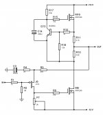
I forgot to say, if you are using 2SJ74 (or similar) as the input JFET, you can tie a resistor (or current generator) from the source of the JFET to +12V. Then you can keep the values of R5 and R4 (or even make them larger). I intend to have a ripple-free +12 V, so I can't see any drawback by doing this.
I have sent for J175. They are cheap and Nelson Pass indicated that this part is not critical. The problem I have is the 0.82 ohm resistor as they are nowhere in sight here. Guess I'll have to cobble up the values . C14 was an issue in an earlier post and yet you retained the original value on the redraft. Any comment on that issue??
My power supply will have 33000uf (4) and a 10amp 24vct transformer.
Thanks for your sharing...
My power supply will have 33000uf (4) and a 10amp 24vct transformer.
Thanks for your sharing...
For 0.82 I used 1 ohm and 4.7 ohms in parallel. Check this post: http://www.diyaudio.com/forums/pass-labs/215392-amp-camp-amp-aca-15.html#post3131860
C14 was an issue in an earlier post and yet you retained the original value on the redraft. Any comment on that issue??
The first simulation was with C14=220uF, but this value was to low. 1000 uF or larger should be OK. Regards.
Have all the parts for this circuit and am ready to proceed . I still am a little hazy about what actually happens with this configuration and would ask that someone indicate what adjustment values are in order . I also wondered why no decoupling at voltage input was included??
I tried to find info on mu followers but ran aground on discussions of triode operation . Any hints as to setting this circuit into operation mode would be appreciated.
I tried to find info on mu followers but ran aground on discussions of triode operation . Any hints as to setting this circuit into operation mode would be appreciated.
You can change the output idle current with R18. You can change the distortion and sonic character by changing R10 and R11. You can change the JFET idle current by changing R5. The potentiometer P7 is used to trim for zero offset at the output. Since we are using a JFET as input and plus/minus power supply, we don't need a blocking capacitor at the input. If you want DC blocking, you can add a capacitor in series with R1.
In the process to build myself a desktop amp, I decided to "steal" the "Amp Camp" output stage and you my J175 JFET input stage from my NOStalgia amplifier. The schematic is shown with the simulation result.
Hi,
what is the output impedance? How should I change the schematics to use it with single rail suply +19V?
Thank you.
- Status
- Not open for further replies.
- Home
- Amplifiers
- Pass Labs
- My desk amp - “Amp Camp” - Aleph current source OR???