Hi Everyone
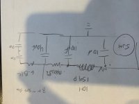
After building a couple of ZKIT2 from decware, and playing around with the power supply (essentially adding capacitance to PS to reduce hum), I decided to embark upon my own build based on the 84CS schematic. I changed up the power supply adding a choke and extra capacitance per my attached drawing. (CLC / RC / RC ) 10H choke and 800ohm resistor yielded correct B+.
I could not unhear 1.1mv hum near field on my 96db speakers with the ZKIT and RC filter, but LOVED the sound of the amp. Now ~200mv. I used PSU designer to simulate, but I am a hobbyist at best.
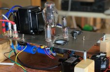
I built on 3mm stainless plate I had made at sendcutsend.com. THIS is a cool service and relatively inexpensive compared to a full chassis. They can laser cut many materials.
It sounds great. The rectifier seems happy.
This is my first scratch build (and 'design'). Now on to woodwork and awaiting transcendar output trannys.
I noted in the various schematics that the value of the grid resistor feeding power tube is either 300 (I built this way), 1K, or 2.7K (ZKIT2). Also the cathode bias resistor is either 100 (I built this way) or 150. I assume this has to do with different supply voltages. The voltages and bias values are all in line in my build so I am not stressing, but I have seen various iterations of the schematic and I am curious.
Also, any feedback on transcendar OPT?
Thanks for reading! 🙂
After building a couple of ZKIT2 from decware, and playing around with the power supply (essentially adding capacitance to PS to reduce hum), I decided to embark upon my own build based on the 84CS schematic. I changed up the power supply adding a choke and extra capacitance per my attached drawing. (CLC / RC / RC ) 10H choke and 800ohm resistor yielded correct B+.
I could not unhear 1.1mv hum near field on my 96db speakers with the ZKIT and RC filter, but LOVED the sound of the amp. Now ~200mv. I used PSU designer to simulate, but I am a hobbyist at best.
I built on 3mm stainless plate I had made at sendcutsend.com. THIS is a cool service and relatively inexpensive compared to a full chassis. They can laser cut many materials.
It sounds great. The rectifier seems happy.
This is my first scratch build (and 'design'). Now on to woodwork and awaiting transcendar output trannys.
I noted in the various schematics that the value of the grid resistor feeding power tube is either 300 (I built this way), 1K, or 2.7K (ZKIT2). Also the cathode bias resistor is either 100 (I built this way) or 150. I assume this has to do with different supply voltages. The voltages and bias values are all in line in my build so I am not stressing, but I have seen various iterations of the schematic and I am curious.
Also, any feedback on transcendar OPT?
Thanks for reading! 🙂
Attachments
With the choke you still arrive at 200mV ripple? That should be lower.
EL84 is a sweet valve when you drive the right loudspeaker.
Try to fixate those big caps, do not let them dingle around by their wires.
EL84 is a sweet valve when you drive the right loudspeaker.
Try to fixate those big caps, do not let them dingle around by their wires.
We went thru 7 iterations starting with the same amp (factory assembled) starting with as close as we get and improving with every iteration.
The PS makes a big difference. We used a hybrid rectifier and CLC supply with all poly caps. We ended up with monBloks. These caps do not need to be huge (they are phusically large and not cheap) but simlier in size.
dave
The PS makes a big difference. We used a hybrid rectifier and CLC supply with all poly caps. We ended up with monBloks. These caps do not need to be huge (they are phusically large and not cheap) but simlier in size.
dave
When you add a choke, you add a device that radiates a magnetic field.
The choke uses all E laminations on one side, and all I laminations on the other side.
A single ended output transformer has all E laminations on one side, and all I laminations on the other side.
The choke can magnetically "Talk" to the output transformer.
Physical separation and proper Orientation of the coils, will help to reduce the "Talking".
And, adding a capacitor can create a Ground Loop.
The Input cap negative lead needs to return Directly to the Center tap of the B+ secondary. That is where the largest transient current in the amplifier is.
Keep the wire short.
A wire is not just a wire.
A wire is a resistor, no matter how small.
A wire is an inductor, no matter how small.
A transient current causes a voltage drop across the wire (resistor; inductor).
Keep the loop away from input circuitry, input grounds, etc.
The voltage drop of a ground loop can interfere with sensitive parts of the amplifier circuits.
A 6922 and 6N1P are not the same.
The mu (u) is the same.
But the Transconductance, and the plate resistance, rp, are different.
So they need different bias and/or different plate load resistors.
And, are you using SV83 output tubes; or are you using EL84 or 6BQ5 output tubes?
EL84 and 6BQ5 are very similar.
SV83 is much different.
Bias Resistors, B+ plate voltages may need to be different.
Some tube rolling is plug and play.
Some tube rolling is plug and Pray.
And, when it comes to single ended output L and R channels, I prefer Individual Self Bias cathode resistors for each cathode (with individual bypass caps across the bias resistors). Double the resistance when you use individual bias resistors, versus a single resistor.
Just my preference.
Have fun building and listening!
Last edited:
The choke can magnetically "Talk" to the output transformer.
I have a 64BG amp where a friend talked me into replacing the OPTs, did not follow my directives and (due entirely to cosmetics) put the OPTs righ tnext to the trafo and it has BAD hum. I have to rejug the chassis and hang the PS trafo off the back of the chassis.
dave
But 6A3’s comment suggests i should try rotating transformers so they may couple less.
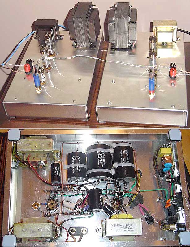
Hi I used a Hammond 159 P. It is under the PT at 90 degrees and OPT are at 90 and shielded by chassis. I haven't heard any talking on amp save for Howard Stern in the morning. I turn on the amp before coffee...
The circuit can run 6N1P / 6922 input tubes and 6P15P/EL84 tubes. Ive tried all.
6N1P on driver tube is best, lean toward 6P15P on detail but EL84 is warmer.
Oh and I used separate resistors for each output bias. 200 ohms each. And each has a meter. The meters were remarkably helpful in diagnostics! And I need to do a final set of measurements to get exact #'s... been too busy listening!
Can you tell me more on how you wired up the meters? I am building two monos Decware SE as well and would like to try add the meter as well.
I would also like to add the 0a3 voltage regulator tube, but I haven't found a schematic with the necessary changes yet.
I would also like to add the 0a3 voltage regulator tube, but I haven't found a schematic with the necessary changes yet.
tubularfluxus,
0A3:
What are you going to do with a 0A3 105V regulator tube?
Are you using it as a reference voltage to run a series regulator triode/pentode/beam tube?
If you use the 0A3 in series with B+ for the input tubes, the new B+ voltage will not be regulated.
A schematic of what you are going to do would be helpful to us.
Meter:
Suppose a self bias resistor is 200 Ohms, and the output tube current is 35mA.
That will be 7 Volts across the self bias resistor.
If you connect a 1mA meter in series with a 10k Ohm resistor, that becomes a 10V meter.
(10k connected to the plus of the meter).
Connect the 10k to the top of the 200 ohm self bias resistor, and the meter negative to ground.
The needle will go to 70% of full scale, that is 7V.
7V/200 Ohms is 35mA.
There is an additional 0.7mA through the meter, the cathode current is 35.7mA.
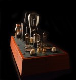
Well...I just like the glow of the OA3 / OD3 and I would like to incorporate it in my Decware SE, as Decware did in their latest Zen Triode 25th year anniversary model.
I don't know much about it. I read quickly its data sheet, but I'm still pretty confuse on how I could integrate it in the existing Decware SE power supply (same as what tubebob posted).
That's why I was hoping in finding a schematic to better understand how to wire it 😕
I don't know much about it. I read quickly its data sheet, but I'm still pretty confuse on how I could integrate it in the existing Decware SE power supply (same as what tubebob posted).
That's why I was hoping in finding a schematic to better understand how to wire it 😕
Attachments
tubularfluxus,
Meter:
Suppose a self bias resistor is 200 Ohms, and the output tube current is 35mA.
That will be 7 Volts across the self bias resistor.
If you connect a 1mA meter in series with a 10k Ohm resistor, that becomes a 10V meter.
(10k connected to the plus of the meter).
Connect the 10k to the top of the 200 ohm self bias resistor, and the meter negative to ground.
The needle will go to 70% of full scale, that is 7V.
7V/200 Ohms is 35mA.
There is an additional 0.7mA through the meter, the cathode current is 35.7mA.
Thank you so much for the explanation! I'm going to look for a compatible good old meter to use!
Example "pretty tube" application.
0D3
Takes 185V to ionize.
Once ionized, it drops to 150V
It is rated for 5 to 40mA.
Let's pick 7mA, not too much dissipation, but enough to keep it from extinguishing (it might need slightly more than 5 mA).
7mA = 0.007A
Start with a 280V B+.
280V - 150V = 130V drop in a series resistor
130V/0.007A = 18,571 Ohms
130V/20k Ohms = 0.0065A; 6.5mA, call it good (use 20k Ohms)
0.0065A x 130V = 0.845 Watts heat in the resistor. Use a 3W 20k resistor.
280V to 20k, 20k to 0D3 plate, 0D3 internal plate to cathode, cathode to ground.
Looks great!
Just calculate according to your B+, and the type of tube you pick.
An 0A3 ionizes at 155V, then stabilizes at 105V, works from 5 to 30mA (pick 7mA).
B+ -105V to calculate the voltage drop of the series resistor. Voltage drop across the resistor/7mA = resistance required.
Etc.
I have no way to know what tube bob posted.
Last edited:
- Home
- Amplifiers
- Tubes / Valves
- My Decware clone, Choke based PS