revell said:Hi, this being my first digital project, that involves soldering,😀
i have some questions : (I attached a picture to clarifie)
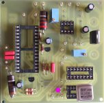
- Is the orientation of the clock correct this way
- the 20 uf elco near the clock : is the + and - correct
Thanks
Hi
pin 1 is at the dot. Pin 4 is down, right. This pin is ground. Pin 5 is the output, upper right.
clock sits correctly (there needs to be a wire jumper under the PCB to connect the pin under the corner with the "T" of the word Tent to connect to the positive lead coming from the regulator (the lower of the two long jumpers you have on top of the PCB).
The caps positive lead should also be oriented to the trace coming from the lower jumper, just the way you have marked it on the image. Or use some non-polar Blackgates and you don't have that problem ;-)
Peter
The caps positive lead should also be oriented to the trace coming from the lower jumper, just the way you have marked it on the image. Or use some non-polar Blackgates and you don't have that problem ;-)
Peter
Hi,
One other advice, use some proper sockets next time for the ic's.
These cheap ones are
Gebruik die met gedraaide contacten (rond).
Safes you from fustration later 🙂
mvg,
One other advice, use some proper sockets next time for the ic's.
These cheap ones are
Gebruik die met gedraaide contacten (rond).
Safes you from fustration later 🙂
mvg,
- Status
- Not open for further replies.