Hello, welcome to my custom RCA70D turntable from 1938.
I call it a RCA70D but it actually is not exactly that, in fact I have not been able to find another like it anywhere on the web and to this day I have no idea what model I have.
However I did manage to find the exact patent.
So how does my model differ to the 70D? Well I will explain that shortly but the mechanics of my unit are almost exactly the same.
Did you know the RCA 70D actually runs a planetary gearbox, in fact models that can play 45's run two different planetary gearboxes.
So a bit of background to my RCA 70D:
It was 1998 and I was in my 20's and totally obsessed with cutting records and cutting lathes. I spent my spare time tracking down leads on equipment and that is when I met an 85 yr old bloke (forgotten his name) who was having a fire sale at his recording studio at Taylor Square in Sydney. He started his studio (It was called "Studio 20") in the 1930's I believe and he had a fire go through the place and had a chalk board up saying "Old recording equipment for sale".
For a young fellow it was an overwhelming obsession hit with virtually everything old and good that I could ever imagine. So he told me he had several cutting lathes but they were buried somewhere behind a wall of other stuff. This man was very frail and old and was very difficult to deal with, constantly vague about a price and reminiscing about how much all this stuff cost new.
He could never give me a price and could never turn up the things I wanted. I hounded him every week and finally he called me and said he had the lathe out for me - a Presto 14B. EXCITED!!!!
It was my first lesson that these things were industrial work horses with the cast iron base weighing in at around 70kg. It was incomplete and looking rough and in a few years, before being restored it would be stolen along with a bunch of race car parts from my garage, breaking my heart and ending the dream of ever restoring it.
Now this turntable was given to me as the platter for the lathe and of course it wasn't, it didn't fit the lathe at all and I was left wondering where it came from.
Forward the clock to now and here I am with a somewhat identified RCA platter, planetary gearbox/bearing and flywheel. What to do with it????
Make it into a belt drive and get it playing records again!!
Some pic of the condition of the parts I have:
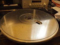
The platter was corroded and pitted:
The platter attached to its spindle and the flywheel. The flywheel was in quite good condition but was later found to be warped, as I write this is is at a machinist who is truing it up:
The main difference of this platter to the RCA70D is that mine has a switch half way along the platter to change the speed from 78 to 33. The RCA 70D has the switch on the outer rim of the platter and has a different linkage for this switch. I do not have any parts for the speed selector switch (you can see these part in the later Patent pic marked 107, 109, 111 and 113.) and so I will be filling this with resin and some weights to help keep the balance.
I 3D modeled the missing material here and it equated to exactly 51.9 grams, that then equates exactly to $6.50 in Australian coins, so I plan to resin in some coins here just for fun, to make it unique and mine.
The underside of a true RCA 70D looks like this:
Mine looks like this, it it almost the same but mine simply has the switch right there in the channel. I can't show any parts of the switch because I don't have any:
Here is a pic of the main spindle with planetary gearbox bearing out of its bearing housing. It will take some time to explain how the gearbox works and I will NOT be using it as
1. the bearing disintegrated while trying to clean it.
2. when running it sounded like 500 freight trains coming though the room. (I cannot believe how any working examples could possibly be working silently and I am sure this machine is why there is a Wow and Flutter measurement at all).
3. while looking for a replacement bearing I was presented with blank stares from industry leading experts. I wish you luck if you ever want to fully restore a RCA 70D. I guess I should tell you now that I have replaced the bearings with Teflon and it is quiet as a mouse!
Also these could quite possibly be the only photos of this machine pulled apart in this state in existence on the web.
The lower bearing face naked but with the flywheel attached, it has this oil pump spiral:
This is the bearing housing, there are parts in here, like the chrome plate with two slots cut in it at 180 degrees to each other, which are parts of the planetary gearbox. Below the plate you may be able to see the original main thrust bearing. This is a huge heavy bearing and although it is in quite good condition, I have replaced it with teflon.
Here is the exact patent for the model I have although it does not say what model it is. It is marked as 1938.
So as much as I want to explain the planetary gearbox from an educational point of view, I'd rather skip it and just move on as my bearing was worn out beyond use and I will be belt driving the whole thing with the belt driving the flywheel and not the platter.
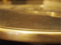
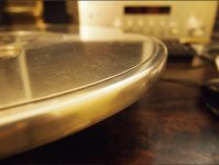
So I spent some time restoring the platter and made some significant mistakes in hitting it with a wire wheel on a drill. It cleaned it up great but scarred the platter pretty bad and I have spent hours sanding out the marks left. I should have just got it hydro blasted.
Anyway, although I don't have great pics of the final result (I am still polishing it), here are some pics of the progress of the platter:
After hitting it with an aggressive wire wheel in the drill, it cleaned up quite nice but I cut some deep marks into the platter which I later came to regret:
Although not the best pics, all the mark are sanded and polished out. This took about 20 hours and I wish I knew about hydro blasting before I did this:
At one point I built this axle and mounted the platter in the forks of this bike. I then used a polish wheel in the drill to spin and polish the platter. This is what one does when they don't have proper tools or money to pay someone else to do it. It worked.
So the platter is pretty much done, I might take it to a professional polisher down the track but I do like the platter to show some battle scars of it's 78 years on earth.
Next (Not exactly in order) I turned to replacing the main bearings with teflon. I went to a plastics supplier who saw me coming and charged me a small fortune to make the ring shaped bearing to replace the originals. I did keep the lower bronze bushing but topped it with a teflon washer which I've compressed into the contour of the spindle and thrust bearing / flywheel so it acts as a support and just makes everything run true. If a certain plastics supply warehouse happens to burn down in the northern suburbs - I have nothing to do with it.
The main bearing replaced, you can see the inner race of the planetary gear bearing with the words "Made In The USA", remember I said this bearing fell apart while I was trying to clean it? Good Riddance!
The lower bronze bushing, this is a before pic, it cleaned up much better than it looks here:
Lower Teflon washer:
Action shot of the flywheel spinning TO THE EXTREME!!!
So the bearing is near silent, in testing it made a bit of noise but I think I just need to bed the Teflon in. The flywheel had a wobble in it and I've sent that off to get machined and I think that was contributing to the noise too. It was virtually silent, I could only hear something with my ear right up to the bearing housing. Did I mention it sounded like 500 freight trains before this?
The Belt Drive:
I have a few options here and I am not totally sure which way I am going to go.
Option 1 - drive it from a Linn motor and power supply that I have surplus. This will work ok but I will have to machine a pulley to the size of the Linn sub platter and attach to the flywheel. The benefit of this is it is a very quiet motor. The disadvantage is I don't have a spare Linn motor and I'd have to upgrade the power supply to run 45rpm. (not that important) It will also ruin the on/off switch design I was going to use because it uses that silly momentary on/off switch and I am hoping to make it look a bit like the original RCA machine with the on/off/on rotary switch.
Option 2 - Go with this Jasmine Belt Drive motor I got off Ebay. You may have seen them. They actually work great but the motor was awfully noisy. I did manage to bed in the bronze bushings in the motor but still it is loud. Too loud to not notice.
Good thing is replacement motors are on ebay for $9 and I've ordered a larger motor with easier access to the bushings which I can condition if they are too noisy. This too was cheap.
From a design point I was thinking of mounting the motor deep in the plinth where the mass of the plinth will absorb most of the sound. I can do this if I drive the platter from the flywheel so I am not too concerned. If I am smart with the design of the plinth I may be able to incorporate both the motor designs and swap them over to find which works best.
Here are some rather terrible videos of it spinning:
https://www.youtube.com/watch?v=oix7LlfnTo0
https://www.youtube.com/watch?v=QWJo8X8lHiw
https://www.youtube.com/watch?v=E8xRfrA439k
Design aesthetics:
So how would you design a plinth for this setup?
I would like it to be a big monolithic beast and was thinking of an aluminum top plate with a plywood layered Plinth. It will be super heavy as mechanics weighs about 15kg all up. I would like to keep it sparse with an old knob as a 33/off/45 rotary selector on the left and a special lit from below RCA logo routered out of the top plate. I have a few ideas to experiment here but I am undecided how to go about it just yet.
I do like the idea of using things I own or come across and have a story, I found this knob in my Dad's garage and I think I will go with this, Even though it is not some RCA original knob, it's from Dad's garage which feels better. It is Bakelite and was in terrible condition but I was able to polish it up using the turntable motor as a polishing motor. It worked really well. Since I took this photo I sanded the white line completely out and it just has a deep circular hole marking the knob position. I might look to put an LED in here to modern it up a bit. Maybe.
Here is a rough mock up of the top plate. Imagine a knob front left and some LEDS shining through the RCA logo, changing color according to the speed selected. and potentially two tonearms.
I have a Jelco 12" arm and one of these new Hana cartridges which I have yet to use.
Anyway that's about it for now, I am awaiting some small parts from ebay to arrive, the flywheel to be machined and then I can get into properly designing the Plinth layers and getting them CNC'd.
Happy days and thanks for looking.
I call it a RCA70D but it actually is not exactly that, in fact I have not been able to find another like it anywhere on the web and to this day I have no idea what model I have.
However I did manage to find the exact patent.
So how does my model differ to the 70D? Well I will explain that shortly but the mechanics of my unit are almost exactly the same.
Did you know the RCA 70D actually runs a planetary gearbox, in fact models that can play 45's run two different planetary gearboxes.
So a bit of background to my RCA 70D:
It was 1998 and I was in my 20's and totally obsessed with cutting records and cutting lathes. I spent my spare time tracking down leads on equipment and that is when I met an 85 yr old bloke (forgotten his name) who was having a fire sale at his recording studio at Taylor Square in Sydney. He started his studio (It was called "Studio 20") in the 1930's I believe and he had a fire go through the place and had a chalk board up saying "Old recording equipment for sale".
For a young fellow it was an overwhelming obsession hit with virtually everything old and good that I could ever imagine. So he told me he had several cutting lathes but they were buried somewhere behind a wall of other stuff. This man was very frail and old and was very difficult to deal with, constantly vague about a price and reminiscing about how much all this stuff cost new.
He could never give me a price and could never turn up the things I wanted. I hounded him every week and finally he called me and said he had the lathe out for me - a Presto 14B. EXCITED!!!!
It was my first lesson that these things were industrial work horses with the cast iron base weighing in at around 70kg. It was incomplete and looking rough and in a few years, before being restored it would be stolen along with a bunch of race car parts from my garage, breaking my heart and ending the dream of ever restoring it.
Now this turntable was given to me as the platter for the lathe and of course it wasn't, it didn't fit the lathe at all and I was left wondering where it came from.
Forward the clock to now and here I am with a somewhat identified RCA platter, planetary gearbox/bearing and flywheel. What to do with it????
Make it into a belt drive and get it playing records again!!
Some pic of the condition of the parts I have:
The platter was corroded and pitted:
An externally hosted image should be here but it was not working when we last tested it.
The platter attached to its spindle and the flywheel. The flywheel was in quite good condition but was later found to be warped, as I write this is is at a machinist who is truing it up:
An externally hosted image should be here but it was not working when we last tested it.
The main difference of this platter to the RCA70D is that mine has a switch half way along the platter to change the speed from 78 to 33. The RCA 70D has the switch on the outer rim of the platter and has a different linkage for this switch. I do not have any parts for the speed selector switch (you can see these part in the later Patent pic marked 107, 109, 111 and 113.) and so I will be filling this with resin and some weights to help keep the balance.
I 3D modeled the missing material here and it equated to exactly 51.9 grams, that then equates exactly to $6.50 in Australian coins, so I plan to resin in some coins here just for fun, to make it unique and mine.
An externally hosted image should be here but it was not working when we last tested it.
An externally hosted image should be here but it was not working when we last tested it.
The underside of a true RCA 70D looks like this:
An externally hosted image should be here but it was not working when we last tested it.
Mine looks like this, it it almost the same but mine simply has the switch right there in the channel. I can't show any parts of the switch because I don't have any:
An externally hosted image should be here but it was not working when we last tested it.
An externally hosted image should be here but it was not working when we last tested it.
An externally hosted image should be here but it was not working when we last tested it.
Here is a pic of the main spindle with planetary gearbox bearing out of its bearing housing. It will take some time to explain how the gearbox works and I will NOT be using it as
1. the bearing disintegrated while trying to clean it.
2. when running it sounded like 500 freight trains coming though the room. (I cannot believe how any working examples could possibly be working silently and I am sure this machine is why there is a Wow and Flutter measurement at all).
3. while looking for a replacement bearing I was presented with blank stares from industry leading experts. I wish you luck if you ever want to fully restore a RCA 70D. I guess I should tell you now that I have replaced the bearings with Teflon and it is quiet as a mouse!
Also these could quite possibly be the only photos of this machine pulled apart in this state in existence on the web.
An externally hosted image should be here but it was not working when we last tested it.
An externally hosted image should be here but it was not working when we last tested it.
An externally hosted image should be here but it was not working when we last tested it.
The lower bearing face naked but with the flywheel attached, it has this oil pump spiral:
An externally hosted image should be here but it was not working when we last tested it.
This is the bearing housing, there are parts in here, like the chrome plate with two slots cut in it at 180 degrees to each other, which are parts of the planetary gearbox. Below the plate you may be able to see the original main thrust bearing. This is a huge heavy bearing and although it is in quite good condition, I have replaced it with teflon.
An externally hosted image should be here but it was not working when we last tested it.
An externally hosted image should be here but it was not working when we last tested it.
Here is the exact patent for the model I have although it does not say what model it is. It is marked as 1938.
An externally hosted image should be here but it was not working when we last tested it.
So as much as I want to explain the planetary gearbox from an educational point of view, I'd rather skip it and just move on as my bearing was worn out beyond use and I will be belt driving the whole thing with the belt driving the flywheel and not the platter.
So I spent some time restoring the platter and made some significant mistakes in hitting it with a wire wheel on a drill. It cleaned it up great but scarred the platter pretty bad and I have spent hours sanding out the marks left. I should have just got it hydro blasted.
Anyway, although I don't have great pics of the final result (I am still polishing it), here are some pics of the progress of the platter:
After hitting it with an aggressive wire wheel in the drill, it cleaned up quite nice but I cut some deep marks into the platter which I later came to regret:
An externally hosted image should be here but it was not working when we last tested it.
An externally hosted image should be here but it was not working when we last tested it.
An externally hosted image should be here but it was not working when we last tested it.
An externally hosted image should be here but it was not working when we last tested it.
An externally hosted image should be here but it was not working when we last tested it.
An externally hosted image should be here but it was not working when we last tested it.
An externally hosted image should be here but it was not working when we last tested it.
An externally hosted image should be here but it was not working when we last tested it.
Although not the best pics, all the mark are sanded and polished out. This took about 20 hours and I wish I knew about hydro blasting before I did this:
An externally hosted image should be here but it was not working when we last tested it.
An externally hosted image should be here but it was not working when we last tested it.
An externally hosted image should be here but it was not working when we last tested it.
An externally hosted image should be here but it was not working when we last tested it.
At one point I built this axle and mounted the platter in the forks of this bike. I then used a polish wheel in the drill to spin and polish the platter. This is what one does when they don't have proper tools or money to pay someone else to do it. It worked.
An externally hosted image should be here but it was not working when we last tested it.
An externally hosted image should be here but it was not working when we last tested it.
An externally hosted image should be here but it was not working when we last tested it.
So the platter is pretty much done, I might take it to a professional polisher down the track but I do like the platter to show some battle scars of it's 78 years on earth.
Next (Not exactly in order) I turned to replacing the main bearings with teflon. I went to a plastics supplier who saw me coming and charged me a small fortune to make the ring shaped bearing to replace the originals. I did keep the lower bronze bushing but topped it with a teflon washer which I've compressed into the contour of the spindle and thrust bearing / flywheel so it acts as a support and just makes everything run true. If a certain plastics supply warehouse happens to burn down in the northern suburbs - I have nothing to do with it.
The main bearing replaced, you can see the inner race of the planetary gear bearing with the words "Made In The USA", remember I said this bearing fell apart while I was trying to clean it? Good Riddance!
An externally hosted image should be here but it was not working when we last tested it.
An externally hosted image should be here but it was not working when we last tested it.
The lower bronze bushing, this is a before pic, it cleaned up much better than it looks here:
An externally hosted image should be here but it was not working when we last tested it.
Lower Teflon washer:
An externally hosted image should be here but it was not working when we last tested it.
Action shot of the flywheel spinning TO THE EXTREME!!!
An externally hosted image should be here but it was not working when we last tested it.
An externally hosted image should be here but it was not working when we last tested it.
So the bearing is near silent, in testing it made a bit of noise but I think I just need to bed the Teflon in. The flywheel had a wobble in it and I've sent that off to get machined and I think that was contributing to the noise too. It was virtually silent, I could only hear something with my ear right up to the bearing housing. Did I mention it sounded like 500 freight trains before this?
The Belt Drive:
I have a few options here and I am not totally sure which way I am going to go.
Option 1 - drive it from a Linn motor and power supply that I have surplus. This will work ok but I will have to machine a pulley to the size of the Linn sub platter and attach to the flywheel. The benefit of this is it is a very quiet motor. The disadvantage is I don't have a spare Linn motor and I'd have to upgrade the power supply to run 45rpm. (not that important) It will also ruin the on/off switch design I was going to use because it uses that silly momentary on/off switch and I am hoping to make it look a bit like the original RCA machine with the on/off/on rotary switch.
Option 2 - Go with this Jasmine Belt Drive motor I got off Ebay. You may have seen them. They actually work great but the motor was awfully noisy. I did manage to bed in the bronze bushings in the motor but still it is loud. Too loud to not notice.
An externally hosted image should be here but it was not working when we last tested it.
An externally hosted image should be here but it was not working when we last tested it.
An externally hosted image should be here but it was not working when we last tested it.
An externally hosted image should be here but it was not working when we last tested it.
An externally hosted image should be here but it was not working when we last tested it.
An externally hosted image should be here but it was not working when we last tested it.
An externally hosted image should be here but it was not working when we last tested it.
Good thing is replacement motors are on ebay for $9 and I've ordered a larger motor with easier access to the bushings which I can condition if they are too noisy. This too was cheap.
From a design point I was thinking of mounting the motor deep in the plinth where the mass of the plinth will absorb most of the sound. I can do this if I drive the platter from the flywheel so I am not too concerned. If I am smart with the design of the plinth I may be able to incorporate both the motor designs and swap them over to find which works best.
Here are some rather terrible videos of it spinning:
https://www.youtube.com/watch?v=oix7LlfnTo0
https://www.youtube.com/watch?v=QWJo8X8lHiw
https://www.youtube.com/watch?v=E8xRfrA439k
Design aesthetics:
So how would you design a plinth for this setup?
I would like it to be a big monolithic beast and was thinking of an aluminum top plate with a plywood layered Plinth. It will be super heavy as mechanics weighs about 15kg all up. I would like to keep it sparse with an old knob as a 33/off/45 rotary selector on the left and a special lit from below RCA logo routered out of the top plate. I have a few ideas to experiment here but I am undecided how to go about it just yet.
I do like the idea of using things I own or come across and have a story, I found this knob in my Dad's garage and I think I will go with this, Even though it is not some RCA original knob, it's from Dad's garage which feels better. It is Bakelite and was in terrible condition but I was able to polish it up using the turntable motor as a polishing motor. It worked really well. Since I took this photo I sanded the white line completely out and it just has a deep circular hole marking the knob position. I might look to put an LED in here to modern it up a bit. Maybe.
An externally hosted image should be here but it was not working when we last tested it.
An externally hosted image should be here but it was not working when we last tested it.
An externally hosted image should be here but it was not working when we last tested it.
An externally hosted image should be here but it was not working when we last tested it.
An externally hosted image should be here but it was not working when we last tested it.
Here is a rough mock up of the top plate. Imagine a knob front left and some LEDS shining through the RCA logo, changing color according to the speed selected. and potentially two tonearms.
An externally hosted image should be here but it was not working when we last tested it.
I have a Jelco 12" arm and one of these new Hana cartridges which I have yet to use.
Anyway that's about it for now, I am awaiting some small parts from ebay to arrive, the flywheel to be machined and then I can get into properly designing the Plinth layers and getting them CNC'd.
Happy days and thanks for looking.
Last edited:
> mounted the platter in the forks of this bike.
Brilliant.
I have bad memories of maintaining similar platters in the day. But glad someone likes the old stuff.
Brilliant.
I have bad memories of maintaining similar platters in the day. But glad someone likes the old stuff.


I got a working mock up today and got it making sound. I am currently modifying the motor so I just spun it by hand. It is mounted in an Ikea Lack table just for now.
An externally hosted image should be here but it was not working when we last tested it.
An externally hosted image should be here but it was not working when we last tested it.
An externally hosted image should be here but it was not working when we last tested it.
An externally hosted image should be here but it was not working when we last tested it.
An externally hosted image should be here but it was not working when we last tested it.
An externally hosted image should be here but it was not working when we last tested it.
Last edited:
I looked at the photos before reading that, and thought "Where has he hidden the motor and the belt??"I am currently modifying the motor so I just spun it by hand.
Super cool project. Thanks for posting. Growing up, my father had an old "transcription turntable" that was probably from the 1940s. Similar to yours, it had an oversized platter and a flywheel. Not nearly as hefty nor as far offset as yours, but a similar idea on a lesser scale. He had arranged it for two speeds. On and Off. 😛
Hoping to see more and hear more about this. It's a fun project and the fact that you don't have an amazing CNC machine shop in your garage just to do whatever you want, makes it all the more entertaining.
Thanks for the photos
I like it 🙂
(btw ikea offers the same size table model but from pure wood, a bit more bucks but better...)
I like it 🙂
(btw ikea offers the same size table model but from pure wood, a bit more bucks but better...)
I looked at the photos before reading that, and thought "Where has he hidden the motor and the belt??"
Thanks for your comments, it is funny you say this as I do plan to mount the motor inside the plinth. It will be mounted upside down from the top of the plinth using speaker spiders and silicon beer coasters! The motor will then drive the flywheel via a belt and accessing the belt will be from underneath. The speaker spider will allow vertical movement of the motor housing without lateral movement. The spider and silicon will absorb vibration. I have done some preliminary test and it looks like the concept is solid. I did see a commercial deck use a much smaller spider to mount their motor and that is where I got the idea from but I am unsure what their company name was.
Pics on all this are to come. Stay tuned.
Just a note on this Flywheel, I paid quality money to an engineering company to remove a buckle in this flywheel. It came back looking really beautiful and I was happy until I installed it to find it still had a massive buckle.
I wrote them an email requesting they work out a plan of action to fix the problem and get my money worth. They responded positively and they have now took action to fix the problem properly.
This time they plan to true up the largest surface in the lathe, then true all surfaces to this, then bore a shaft insert.
They had machines as large as cars so I hope they can get this right. I would have done it myself if I had a lathe.
An externally hosted image should be here but it was not working when we last tested it.
Last edited:
Just a quick update to say the flywheel has been repaired. The machinist true'd the largest face then cut all othe faces true then bored out a new centre and sleeved it. It is spinning very true now.

Hello, some things have been happening in the background of this build but not worth taking too many pics, I will post some though so hang in there. I've mostly been waiting for the postman to deliver some ebay stuff.
I work in a very heavy industrial area doing overnight shifts so on my meal break I drive around at midnight and see what has been chucked out on the street. This plinth will be built entirely out of wood I found on the side of the road. There are a bunch of kitchen and sign manufacturers in the area so they always chuck out scraps.
I have figured I have enough wood to build a layered plinth of 580mm x580mm from:
8 x 18mm MDF
14 x 6.5mm 5 Ply
But just last night I nabbed a big box made from 4 sheets of 11mm 5 ply so I may use that instead of so many little 6.5mm sheets.
Here is a cross section of the design:
Some things to notice in this plinth design, it will be made in two parts with small (Tiny!) rare earth magnets clamping the two sections together guided by 4 dowels, sealing the drive motor and belt completely inside the plinth and hopefully reducing the motor noise to zero.
So through the middle section where it will split will be the thicker 18mm MDF.
To the left of the lower platter is the motor pod, it will be inverted and suspended by silicon beer coasters ans speaker spiders.
While at a local charity shop I spied about 50 of these silicone beer coasters and grabbed the lot.
These coasters are the exact same diameter as my motor pod!
I ordered a speaker spider repair kit off ebay to a size I thought would suit my motor pod:
...and though an act of HIFI serendipity, the coaster's indented circles lined up perfectly with the corrugations in the spider.
The motor pod also had a 6mm screw tapped in the centre of the bottom plate so I used this to punch a hole in the coaster and mount the suspension like this:
So here is where you'll start needing your imagination as I haven't built the next bit and will need to prototype it to get measurements, The outside diameter of the speaker spider will need to sit in a recessed hole with a locking ring to clamp it in place, this will be cut into one of the top layers and accessed through a hole in the top of the plinth. Later a round plate will be cut to tidy up the top of the plinth and hide the pod below it.
So the pod will be suspended from the top and supported by another spider below. The bottom spider will give much greater support but less suspension as the outer diameter of the pod will be closer to the outer diameter of the spider. In simple testing there is an amazing amount of suspension and support and the pod will virtually float in air, being able to move vertically but restricted laterally. Just like a speaker cone.
There is a wooden washer placed on top to spread the weight of the pod.
Here the top and bottom spiders are in place.
So next step:
I need to figure out exactly ho to mount the bottom spider. If I keep the original pod top with the motor offset from the centre I can rotate the entire assembly to gain correct belt tension and I think the offset will create a stronger lateral tension on the bottom spider and stop it from trying to freely bounce about too much.
The other option is to make a new top plate (out of perspex I have on hand) and locate the motor directly in the centre. I am unsure which design is best.
I also have to build a jig to hold the spiders in place but move their distances closer of further apart so I can see what layer of the plinth needs to mount the spiders. I'll use a circle cut in wood triangle with the correct outer spider dimension and three holes to run all thread dowels to another triangle below. I can then adjust these two pieces of wood to see how far apart the spiders need to be.
This is the bit that is holding up the build for now so on with it I should get.
Oh and I ordered a bunch of ON/OFF/ON switches and there is a story to theses.
I initially bought this one only to discover it would not switch two paralleled switches at once:
So I ordered this big daddy'o only to find the little one actually did switch what I needed. I may still use the big one and maybe just wire it in paralleled as a redundant switch. in case it ever breaks.
This is all after I bought my favorite tactile feeling switch of all of them only to find it definitely would not switch what I needed but it is a beautiful switch:
Oh and last but not least, this is the polished Bakelite knob I found in my Dad's garage. I am going to mount a Blue/Red LED in the little hole on top for 33/45 display.
Thanks for looking and I'll check in again with pictures of the marble slab I picked up which may also make the top plate for this beast... pics to come.
I work in a very heavy industrial area doing overnight shifts so on my meal break I drive around at midnight and see what has been chucked out on the street. This plinth will be built entirely out of wood I found on the side of the road. There are a bunch of kitchen and sign manufacturers in the area so they always chuck out scraps.
I have figured I have enough wood to build a layered plinth of 580mm x580mm from:
8 x 18mm MDF
14 x 6.5mm 5 Ply
But just last night I nabbed a big box made from 4 sheets of 11mm 5 ply so I may use that instead of so many little 6.5mm sheets.
Here is a cross section of the design:
An externally hosted image should be here but it was not working when we last tested it.
Some things to notice in this plinth design, it will be made in two parts with small (Tiny!) rare earth magnets clamping the two sections together guided by 4 dowels, sealing the drive motor and belt completely inside the plinth and hopefully reducing the motor noise to zero.
So through the middle section where it will split will be the thicker 18mm MDF.
To the left of the lower platter is the motor pod, it will be inverted and suspended by silicon beer coasters ans speaker spiders.
While at a local charity shop I spied about 50 of these silicone beer coasters and grabbed the lot.
An externally hosted image should be here but it was not working when we last tested it.
These coasters are the exact same diameter as my motor pod!
An externally hosted image should be here but it was not working when we last tested it.
I ordered a speaker spider repair kit off ebay to a size I thought would suit my motor pod:
An externally hosted image should be here but it was not working when we last tested it.
...and though an act of HIFI serendipity, the coaster's indented circles lined up perfectly with the corrugations in the spider.
An externally hosted image should be here but it was not working when we last tested it.
The motor pod also had a 6mm screw tapped in the centre of the bottom plate so I used this to punch a hole in the coaster and mount the suspension like this:
An externally hosted image should be here but it was not working when we last tested it.
So here is where you'll start needing your imagination as I haven't built the next bit and will need to prototype it to get measurements, The outside diameter of the speaker spider will need to sit in a recessed hole with a locking ring to clamp it in place, this will be cut into one of the top layers and accessed through a hole in the top of the plinth. Later a round plate will be cut to tidy up the top of the plinth and hide the pod below it.
So the pod will be suspended from the top and supported by another spider below. The bottom spider will give much greater support but less suspension as the outer diameter of the pod will be closer to the outer diameter of the spider. In simple testing there is an amazing amount of suspension and support and the pod will virtually float in air, being able to move vertically but restricted laterally. Just like a speaker cone.
There is a wooden washer placed on top to spread the weight of the pod.
Here the top and bottom spiders are in place.
An externally hosted image should be here but it was not working when we last tested it.
So next step:
I need to figure out exactly ho to mount the bottom spider. If I keep the original pod top with the motor offset from the centre I can rotate the entire assembly to gain correct belt tension and I think the offset will create a stronger lateral tension on the bottom spider and stop it from trying to freely bounce about too much.
The other option is to make a new top plate (out of perspex I have on hand) and locate the motor directly in the centre. I am unsure which design is best.
I also have to build a jig to hold the spiders in place but move their distances closer of further apart so I can see what layer of the plinth needs to mount the spiders. I'll use a circle cut in wood triangle with the correct outer spider dimension and three holes to run all thread dowels to another triangle below. I can then adjust these two pieces of wood to see how far apart the spiders need to be.
This is the bit that is holding up the build for now so on with it I should get.
Oh and I ordered a bunch of ON/OFF/ON switches and there is a story to theses.
I initially bought this one only to discover it would not switch two paralleled switches at once:
An externally hosted image should be here but it was not working when we last tested it.
So I ordered this big daddy'o only to find the little one actually did switch what I needed. I may still use the big one and maybe just wire it in paralleled as a redundant switch. in case it ever breaks.
An externally hosted image should be here but it was not working when we last tested it.
This is all after I bought my favorite tactile feeling switch of all of them only to find it definitely would not switch what I needed but it is a beautiful switch:
An externally hosted image should be here but it was not working when we last tested it.
Oh and last but not least, this is the polished Bakelite knob I found in my Dad's garage. I am going to mount a Blue/Red LED in the little hole on top for 33/45 display.
An externally hosted image should be here but it was not working when we last tested it.
Thanks for looking and I'll check in again with pictures of the marble slab I picked up which may also make the top plate for this beast... pics to come.
Thanks for the updates and the photos.
Can you do us a favor and resize your photos for web use? 1024 pixels wide is plenty big for the forum.
Please see here: http://www.diyaudio.com/forums/everything-else/183084-pictures-why-not-attach-them.html
Can you do us a favor and resize your photos for web use? 1024 pixels wide is plenty big for the forum.
Please see here: http://www.diyaudio.com/forums/everything-else/183084-pictures-why-not-attach-them.html
Hi I have resized the pics in my original 1st post because they were a bit unfriedly size and it caused a few problems. I also added a few more but I have been unable to edit my post 5 and post 12 but I have resized pics waiting if I could only edit the post...
Last edited:
An Update,
My mate who was going to CNC my plinth had a flood and his CNC machine was destroyed. So after an almost 6 month delay, he has a new machine and soon he will work on my plinth. One small problem is he doesn't like my motor suspension idea and wants to redesign the entire motor and speed control. This kinda ***** me because I like my idea and it is mine. So I hope he can convince me with his new design.
It is hard relying on friends to help you because it takes the control away form me.
In other news, I managed to "acquire" a slab of 60mm and two slabs of 20mm white marble. That stuff is heavy!!!
So I think I will use these bits to make a marble, wood sandwich plinth.
some pics to come soon.
Unfortunately we see in this thread the dangers of off site photo hosting. Almost all your cool photos are now gone. 🙁
Good luck with the continuation of your project.
Good luck with the continuation of your project.
- Status
- Not open for further replies.
- Home
- Source & Line
- Analogue Source
- My Custom 1938 RCA 70D