Hi All,
It started out in life as a humble Marantz CD6000OSE and then i got the notion to fit a low jitter clock module.
If anyone was thinking of going down this 'road' then I thought I would share my experience so that you may make a more informed decision about doing it.
I bought an Audiocom upgrade "kit one" - from unplugging the CDP to plugging it back in took about 3hrs.
Firstly, electronics is not my forte and apart from the occasional bit of soldering this is my first project. So, yes I am definitely a novice at this.
Before starting this I picked up an old TV of the street and pulled the motherboard out of it. I then practised de-soldering parts until I felt that i knew what to do without damaging the component or the PCB. I would recommend that you do the same thing - go into your shed/loft find an old 'trany' and get practising. **** At your own risk ****
As stated in the written instructions - "disconnect the mains supply before removing the lid of your player."
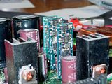
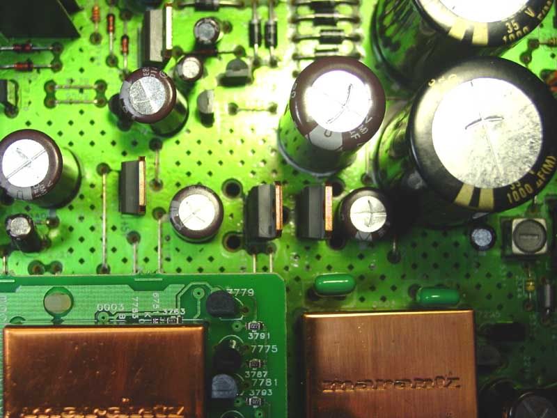
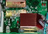
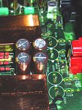
1. After lid removal I identified the components to be de-soldered.
Clock & Cap's.
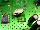
Original regulators.
DC power "take off".

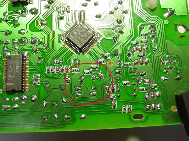
Clock location on underside of board.

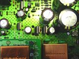
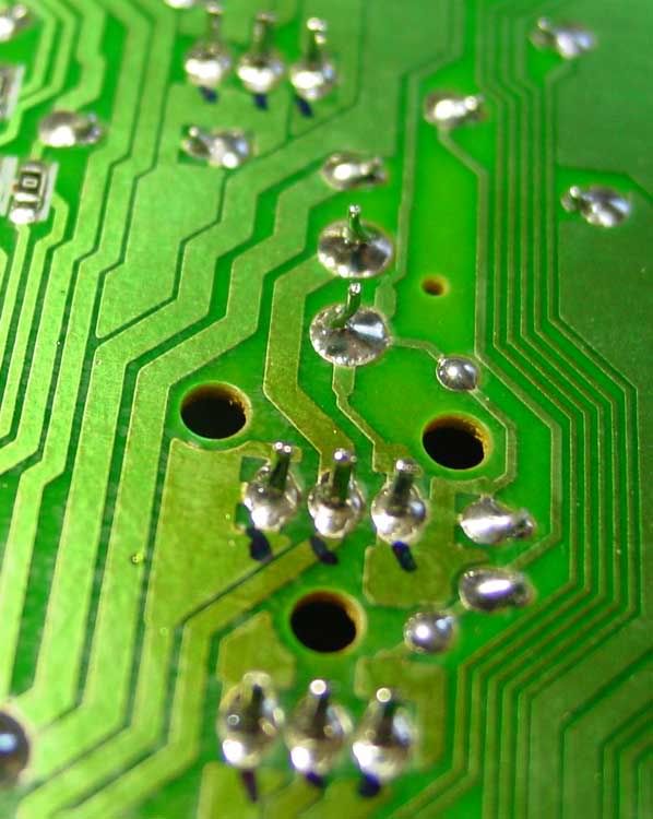
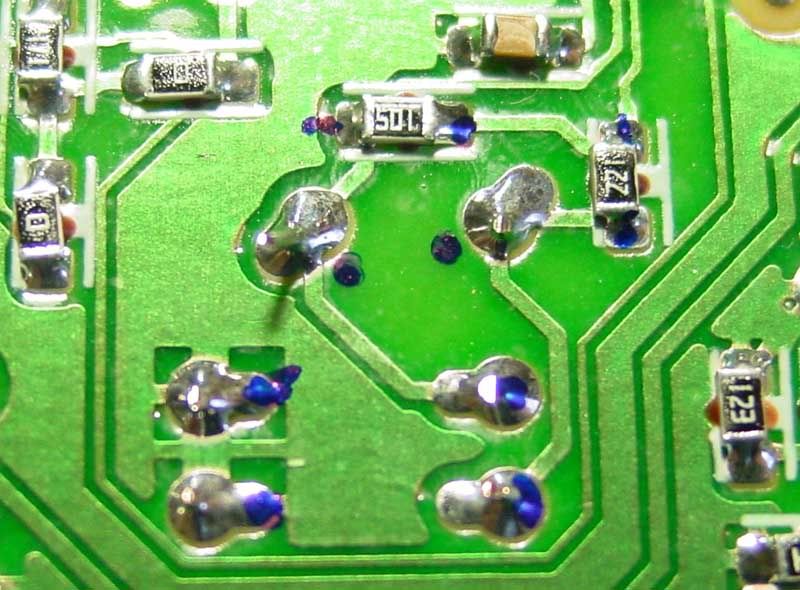
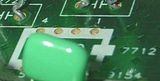
2. I then marked each solder join for easy un-interrupted de-soldering.
Reg's

Clock,cap's and smd's
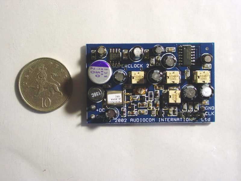
3. Then I looked at the new components to be fitted and worked out the best way of fitting them.
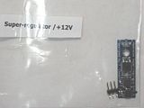
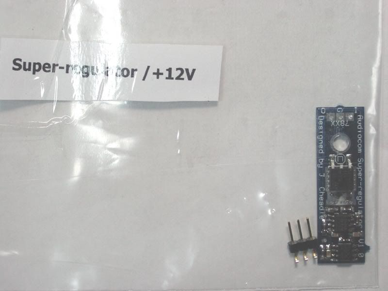
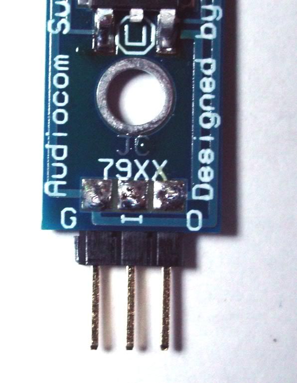
4. The new reg's are unmarked so I left them in their bags - removed one for sizing up purposes.
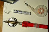
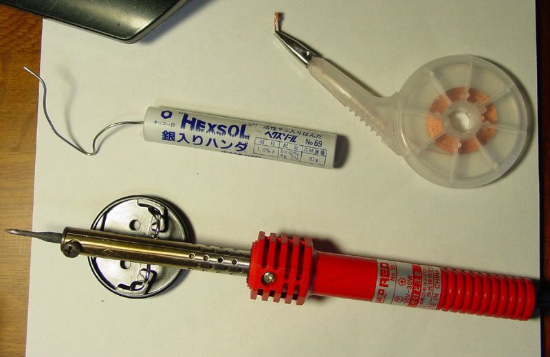
5. Tools required.
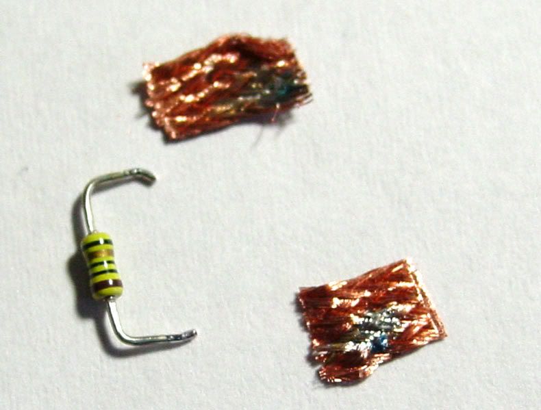
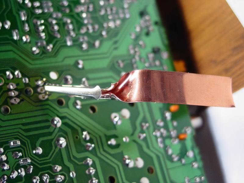
6. A capacitor removed with the de-solder wick showing how much comes off.
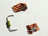
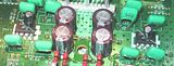
7. The components all removed.
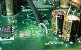
8. Soldered regulator.

9. Fitting new reg's with a homemade heat sink.

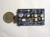
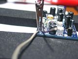
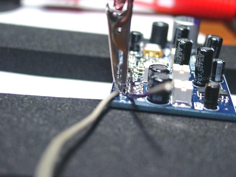
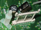
10.Putting on Power, clock and ground cables onto the superclock PCB. *** Make sure to use single core cable for the CLK & GRD connections***You can also use high quality coaxial cable as it allows longer lengths to be used with out effecting the signal***

11.All parts soldered.
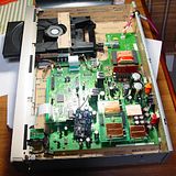
12.Re-assembled.
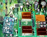
13.Additional image to show how the new reg's sit.
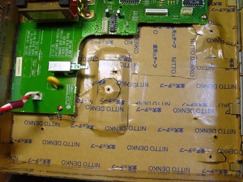
14.Deadening I had previously fitted.

Tips.
1. Don't wear man-made fabrics like 'Fleece's' too avoid static build-up.
2. When working with hot tools always take your time and be methodical in what you are doing.
3. When soldering try and support your hand, saves getting the 'shakes'. I used a 500g tea tin.
4. When de-soldering, after each solder join cut the wick and start the next one with a clean piece. This also allows time for the component to cool before applying heat to its next leg and for you to get your composure back.
5. When things are going well don't "rush on", keep to a good rhythm and the job will get done.
6. keep your work area well ventilated - some nasty gases come of solder/flux.
7. keep your work area well illuminated.
8. Have varying sizes of foam for making packers while soldering parts in, or for isolating/insulting between parts.
9. Don't apply the soldering iron beyond 5sec's, and try using a heat sink whenever possible.
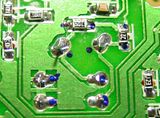
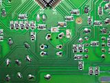
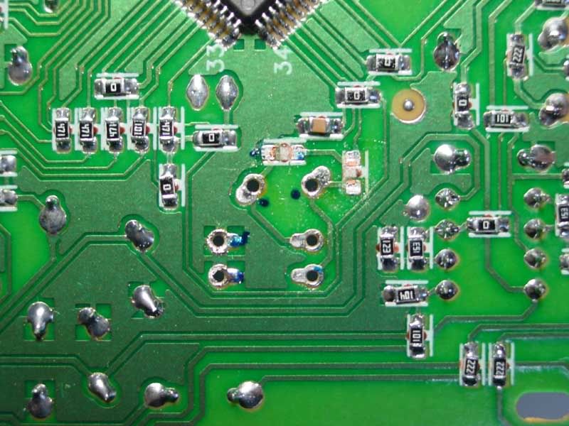
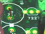
The only things which didn't fall off after de-soldering was the 'minute' SMD resistors on the solder join side of the motherboard. I used the soldering irons tip for about 1.5 sec to 'pop' them off.
more to come ......
It started out in life as a humble Marantz CD6000OSE and then i got the notion to fit a low jitter clock module.
If anyone was thinking of going down this 'road' then I thought I would share my experience so that you may make a more informed decision about doing it.
I bought an Audiocom upgrade "kit one" - from unplugging the CDP to plugging it back in took about 3hrs.
Firstly, electronics is not my forte and apart from the occasional bit of soldering this is my first project. So, yes I am definitely a novice at this.
Before starting this I picked up an old TV of the street and pulled the motherboard out of it. I then practised de-soldering parts until I felt that i knew what to do without damaging the component or the PCB. I would recommend that you do the same thing - go into your shed/loft find an old 'trany' and get practising. **** At your own risk ****
As stated in the written instructions - "disconnect the mains supply before removing the lid of your player."
1. After lid removal I identified the components to be de-soldered.
Clock & Cap's.

Original regulators.
DC power "take off".
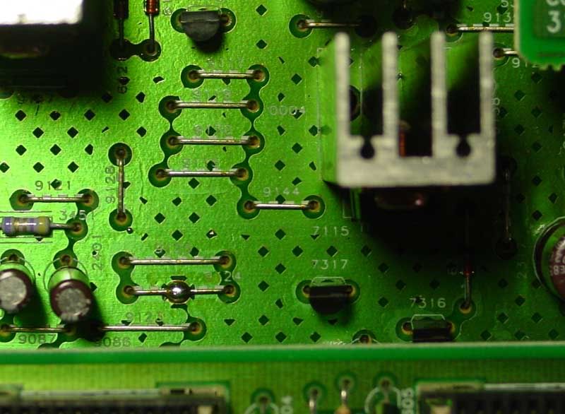
Clock location on underside of board.
2. I then marked each solder join for easy un-interrupted de-soldering.
Reg's
Clock,cap's and smd's
3. Then I looked at the new components to be fitted and worked out the best way of fitting them.
4. The new reg's are unmarked so I left them in their bags - removed one for sizing up purposes.
5. Tools required.
6. A capacitor removed with the de-solder wick showing how much comes off.
7. The components all removed.
8. Soldered regulator.
9. Fitting new reg's with a homemade heat sink.
10.Putting on Power, clock and ground cables onto the superclock PCB. *** Make sure to use single core cable for the CLK & GRD connections***You can also use high quality coaxial cable as it allows longer lengths to be used with out effecting the signal***
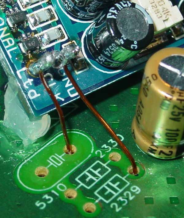

11.All parts soldered.

12.Re-assembled.

13.Additional image to show how the new reg's sit.

14.Deadening I had previously fitted.
Tips.
1. Don't wear man-made fabrics like 'Fleece's' too avoid static build-up.
2. When working with hot tools always take your time and be methodical in what you are doing.
3. When soldering try and support your hand, saves getting the 'shakes'. I used a 500g tea tin.
4. When de-soldering, after each solder join cut the wick and start the next one with a clean piece. This also allows time for the component to cool before applying heat to its next leg and for you to get your composure back.
5. When things are going well don't "rush on", keep to a good rhythm and the job will get done.
6. keep your work area well ventilated - some nasty gases come of solder/flux.
7. keep your work area well illuminated.
8. Have varying sizes of foam for making packers while soldering parts in, or for isolating/insulting between parts.
9. Don't apply the soldering iron beyond 5sec's, and try using a heat sink whenever possible.
The only things which didn't fall off after de-soldering was the 'minute' SMD resistors on the solder join side of the motherboard. I used the soldering irons tip for about 1.5 sec to 'pop' them off.
more to come ......
Looks good and the advice you give is sound. Only the use of a heatsink during soldering would not be my recommendation. In my 8+ years of experience in electronics I found that (de)soldering pins that are connected to big tracks or groundplanes is hard. The resaon being the large amount of copper drawing heat from the tip of the iron. Actually, it acts as a heatsink. This means you need more heat and a longer time to finish the job => more risk of damaging the component (not less). Try some joins without the heatsink, you'll see what I mean.
The only beneficial use of a heatsink is with really heat sensitive components with long leads. If you put a heatsink on the lead between the body of the component and the end of the lead to be soldered, excess heat traveling up the lead will largely end up in the heatsink instead of the component itself.
The only beneficial use of a heatsink is with really heat sensitive components with long leads. If you put a heatsink on the lead between the body of the component and the end of the lead to be soldered, excess heat traveling up the lead will largely end up in the heatsink instead of the component itself.
Next set of mod's
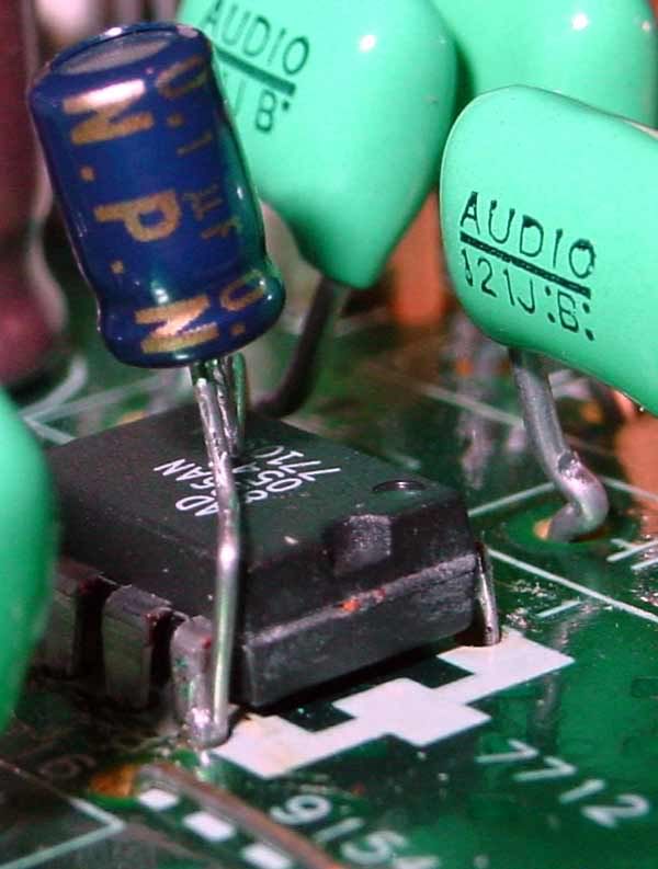
........ The ICs are meant to transmit a lot of RFI so cant hurt to block it. I made sure that no part of the shield is touching anything but silicon.

These next set of mod's were recommended to me by a gentleman by the name of Magnus, a bit of a Marantz Guru
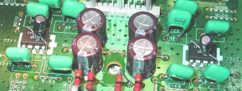
Recommended to remove the HDAM units up on the stilts and replace them with some op-amp's

1)I identified where the op-amp's were to be located and the PCB showed which way to install them.
2)Did't have Cerafines under the HDAM module that most of these players have .
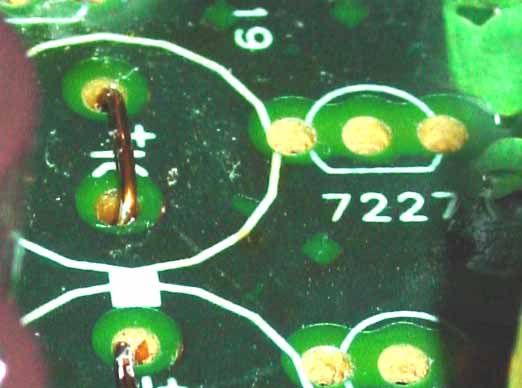
3)Removed the Silmics, Muting transistors and the other two cap's as recommended.

4)Bridged the + & - terminals together where the Silmics were.
5)Swapped the standard Elnas for the Silmics.
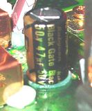
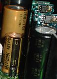
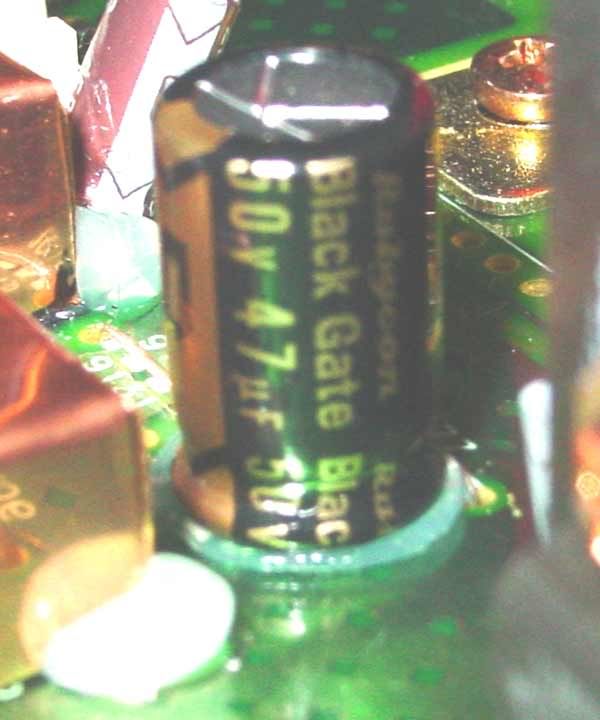
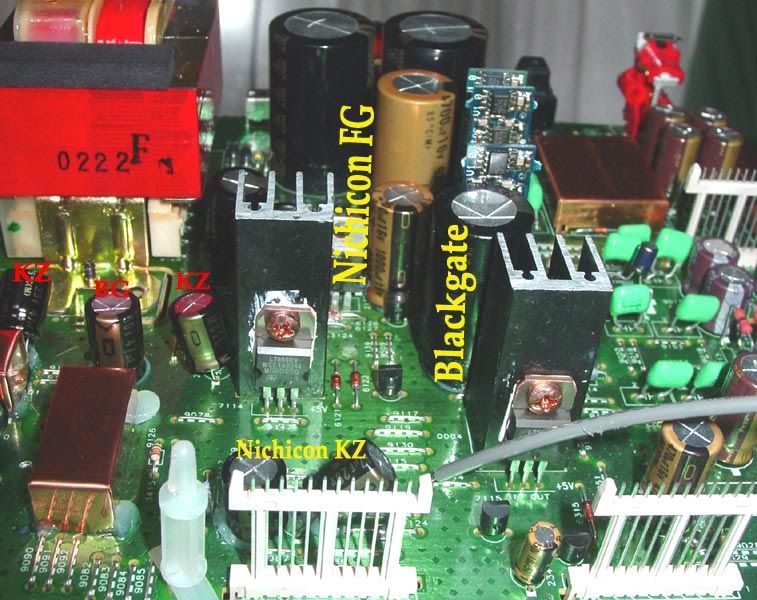
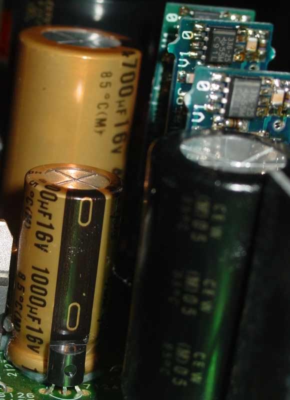
6)Replaced the 6.3v Elna beside the +5v super reg' with a Blackgate 16v one.
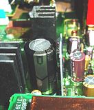
7)Replaced the 35v Elna with a Blackgate 50v cap'.
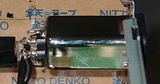
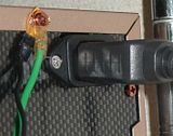
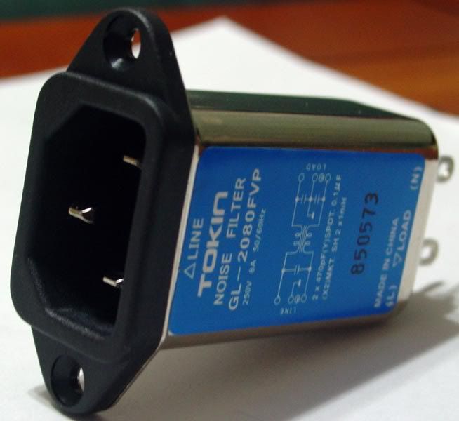
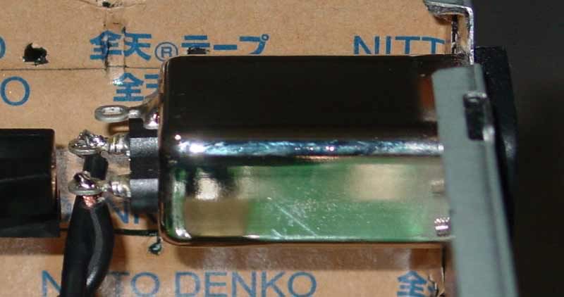
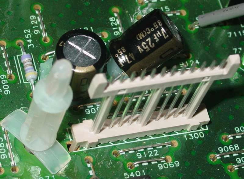
I had soldered the power supply cable directly onto the board but with the lid coming off and back on so many times i decided to put one of these in;I measured up the power unit and marked out the back casing. This was then removed and I drilled four holes (8mm) at each corner inset by 4mm equally - this gives a nice quarter radius at each corner matching the Tokins profile. I then used my Jigsaw with a fine 'metal' blade and removed the unwanted material, gave all the new cut edges a file with a half round blade and placed the unit into the new hole. Next I marked up the drill points for the two fixings and drilled them out with a 3.2mm bit, the unit is secured using two 3mm * 10mm countersunk philip heads. As you can see from the photo the reach into the player couldn't of been much closer to the loader!Phew!!


The Op-amps went into the pin holes fairly well with me just giving them a gentle push. Before fully setting them into place I inserted the legs of the capacitor into the 4 & 8 holes and then pushed both units down (gently) together. I had pre-formed the cap's legs before starting...

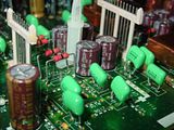
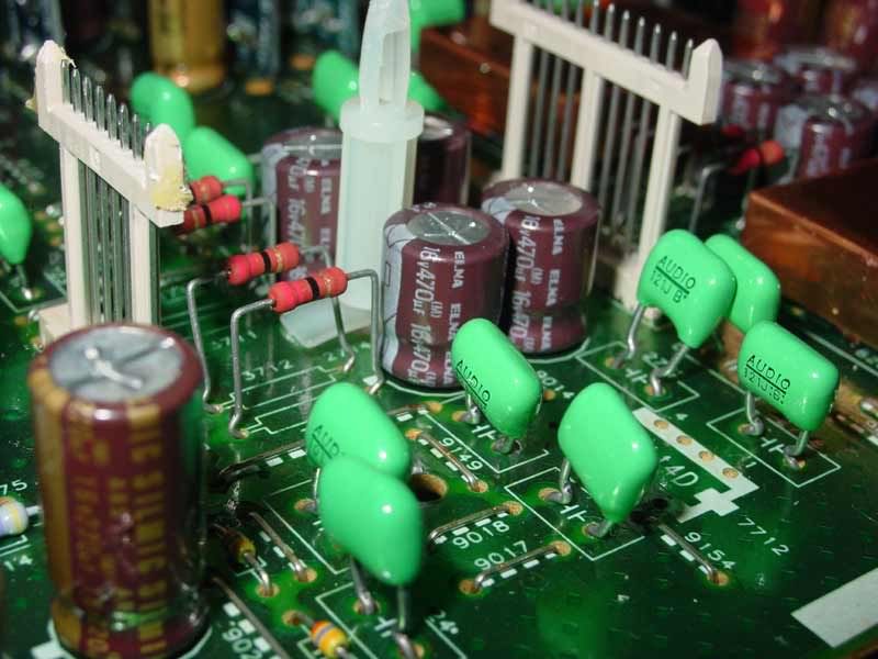
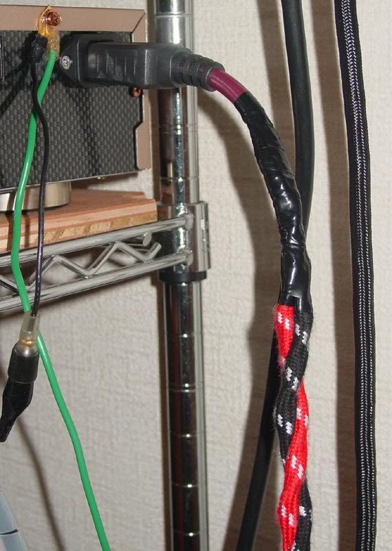
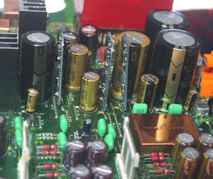
Then it was time to start replacing the standard cap's for something a bit more exotic and trying out some home made power cables too;


more to come ......
........ The ICs are meant to transmit a lot of RFI so cant hurt to block it. I made sure that no part of the shield is touching anything but silicon.
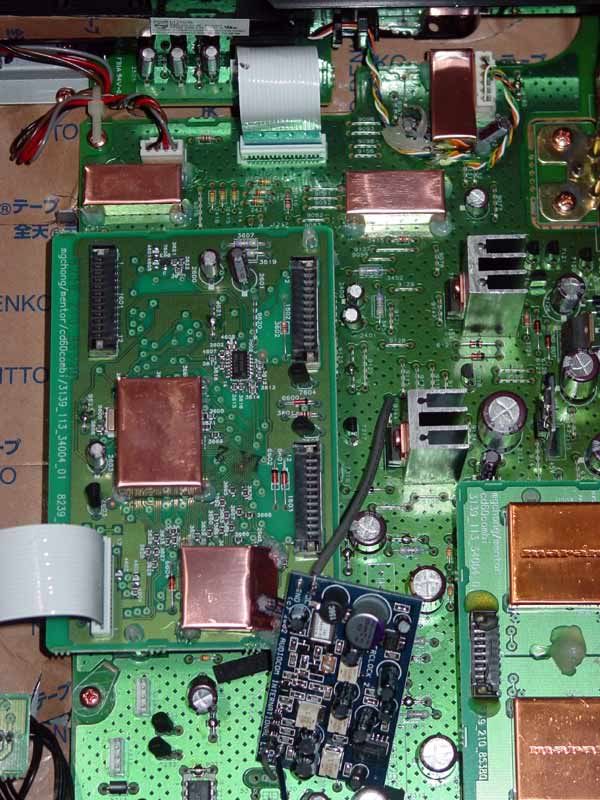
These next set of mod's were recommended to me by a gentleman by the name of Magnus, a bit of a Marantz Guru
Recommended to remove the HDAM units up on the stilts and replace them with some op-amp's
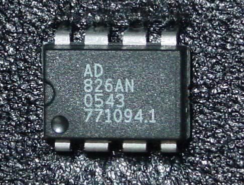
1)I identified where the op-amp's were to be located and the PCB showed which way to install them.

2)Did't have Cerafines under the HDAM module that most of these players have .
3)Removed the Silmics, Muting transistors and the other two cap's as recommended.
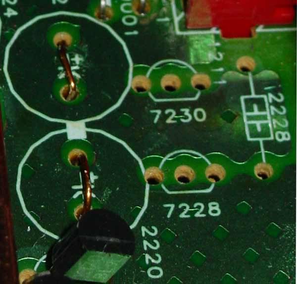
4)Bridged the + & - terminals together where the Silmics were.
5)Swapped the standard Elnas for the Silmics.

6)Replaced the 6.3v Elna beside the +5v super reg' with a Blackgate 16v one.

7)Replaced the 35v Elna with a Blackgate 50v cap'.
I had soldered the power supply cable directly onto the board but with the lid coming off and back on so many times i decided to put one of these in;I measured up the power unit and marked out the back casing. This was then removed and I drilled four holes (8mm) at each corner inset by 4mm equally - this gives a nice quarter radius at each corner matching the Tokins profile. I then used my Jigsaw with a fine 'metal' blade and removed the unwanted material, gave all the new cut edges a file with a half round blade and placed the unit into the new hole. Next I marked up the drill points for the two fixings and drilled them out with a 3.2mm bit, the unit is secured using two 3mm * 10mm countersunk philip heads. As you can see from the photo the reach into the player couldn't of been much closer to the loader!Phew!!

The Op-amps went into the pin holes fairly well with me just giving them a gentle push. Before fully setting them into place I inserted the legs of the capacitor into the 4 & 8 holes and then pushed both units down (gently) together. I had pre-formed the cap's legs before starting...
Then it was time to start replacing the standard cap's for something a bit more exotic and trying out some home made power cables too;
more to come ......
- Status
- Not open for further replies.