At the end of September, SSAudio (Burson) commented on the ‘The best sounding audio integrated opamps’ thread offering free samples of their Supreme Sound Op-Amp V5 and V6 range. I was lucky enough to have my proposal accepted and they agreed to send me a couple of the V6 Classics to try out. In return, they requested that I document a project and express my thoughts of their product.
A few of points of preamble. I am just an ordinary DIYer. Anything presented in the thread is how I did things but does not constitute a recommendation for how you should do things. If anything here causes you to burn your house down, electrocute the cat, whatever – that is your responsibility and problem.
Secondly, you might copy everything I did but it may sound rubbish to you. Or it might sound better. I don’t have ‘golden ears’ or claim to have any special ability when it comes to listening – my hearing rolls off at 13 and 15kHz thanks to a love of Jet engines..
Third, I don’t currently have access to any special testing equipment other than a signal generator and a CRO. I can see gross errors like oscillation and bad waveforms, but I cannot perform THD tests etc. This means that the following will be subjective, not scientific. I’d love nothing more than to compare graphs and figures, but sadly this is going to be a listening and enjoyment exercise with as few clichés as I can stomach (no veils will be lifted in the making of this project 😉).
Lastly, I have no affiliation, affinity etc to Burson other than they sent me a product to play with and asked for my thoughts. I’ve received no payment or benefit other than being able to keep the product.
Delivery
The package took around a month to arrive from Hong Kong. Inside the little Jiffy bag was the product and a couple of zip ties. Not sure what those are intended for, but thanks anyway.

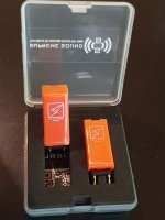
The product comes in a small, hard plastic case with a nice dense foam insert, cut out to fit the opamps snugly. Beneath the foam was a card with a couple of ‘Q’ codes that take you to the product information page on their website.
The first thing that struck me with the product was the logo that it bears. Hmm I’m sure I’ve seen that one before somewhere….

Project
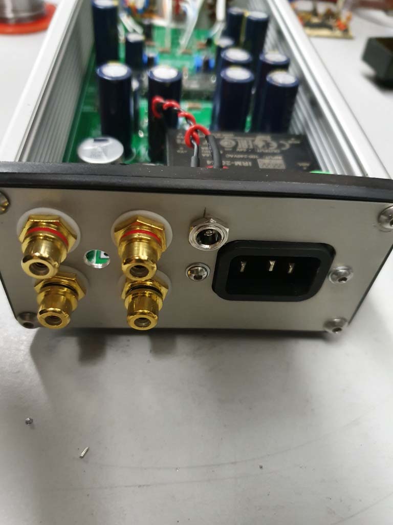
The initial project I chose was to create an inverting buffer to couple with my Korg B1 Buffer (which I use as a headphone amp). The Korg inverts the signal phase and apparently negative H2 distortion is not as nice as positive H2 for some people. When used as a preamp, correcting this is a simple case of switching the speaker lead + and - over, but it’s not so easy when using headphones. I don’t fancy rewiring mine, so a simple NE5532 buffer in inverting configuration is the way I’ll go.
In preparation, I chucked a DC power jack onto the back of the Korg. I am using the PCB from Algar_Emi (GB B1 Nutube PCB with integrated PS) that is equipped with a Meanwell IRM-20-24 900mA power supply that I tapped after the first stage of filtering. The Korg only draws around 60mA or so, so plenty of power left for a couple of NE5532s.
Donor Boards
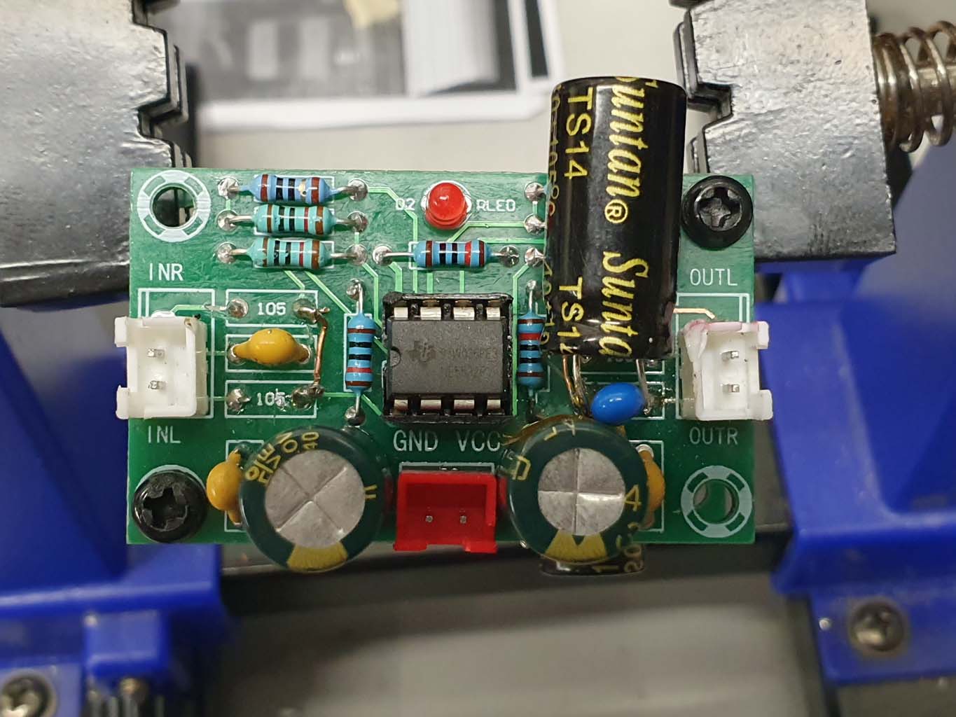
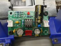
First thing to do was order some cheap ebay NE5532 boards that will suit the task. I chose a single ended supply version with through-hole components for ease of modification, and so that I can piggy-back the 24v power supply off the Korg (rather than needing to create a split supply).
A pack of 5 pre-populated boards set me back $14AUD delivered (or less than $10USD).

Schematic
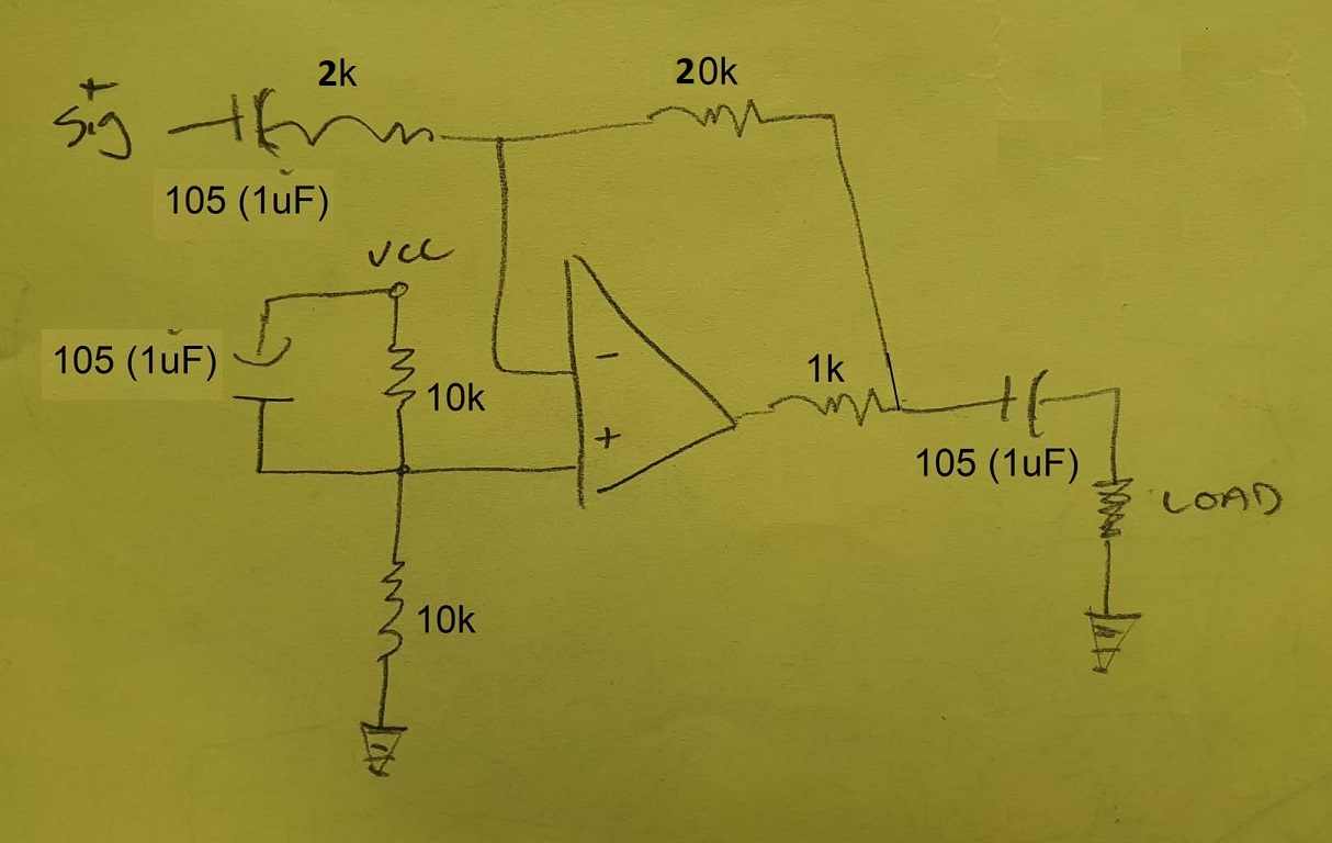
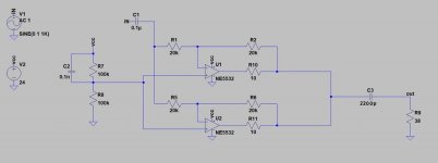
I roughly traced out the schematic from the Ebay board. The capacitor values were higher than expected – 1uF as opposed to 0.1uF from the datasheet. The board is set up as a preamp with a gain of -10 set by way of 2k/20k resistors. There is a 1k at the output of the opamp. As this is a single ended supply, the amp has been biased with a voltage divider at the non-inverting input using 10k resistors – I was expecting 100k in this position, but this seems to work.
Modifications
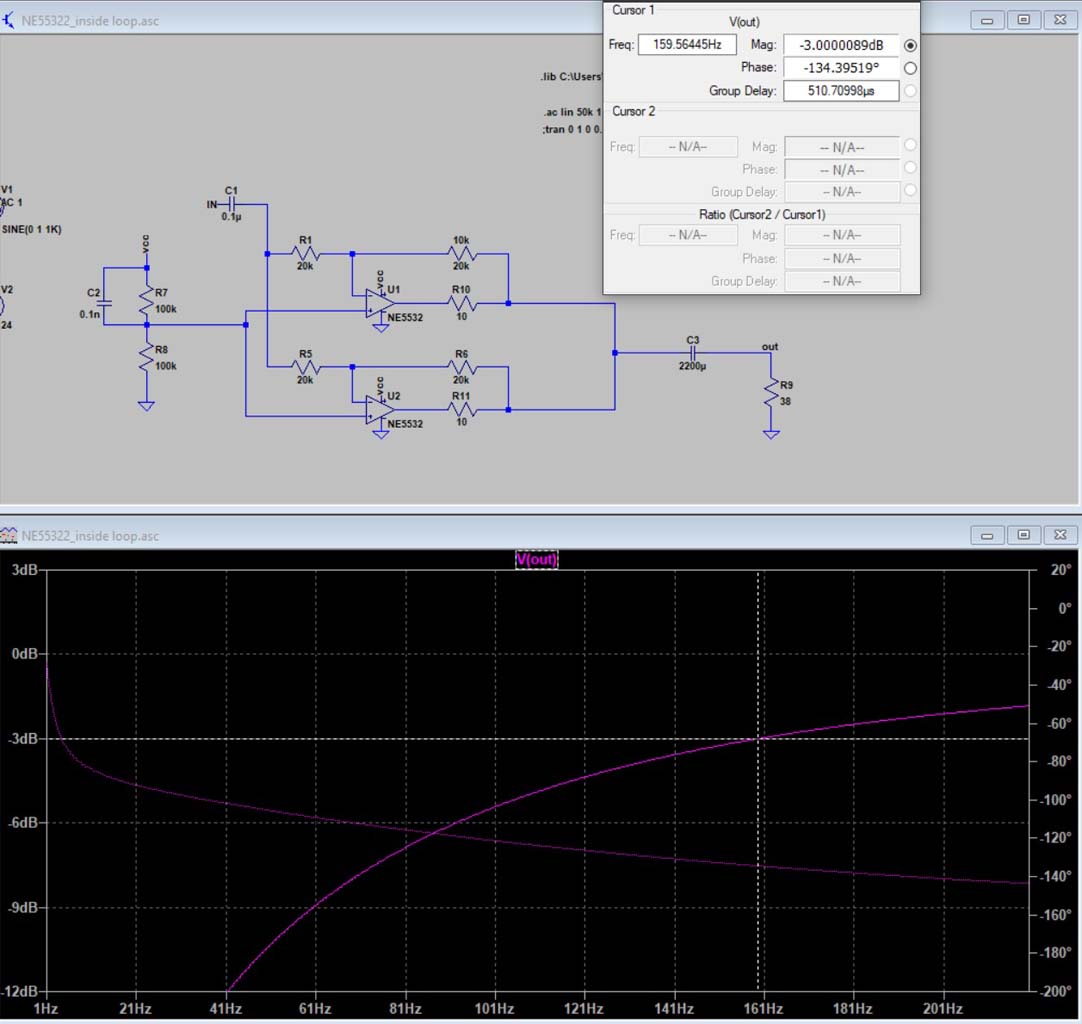
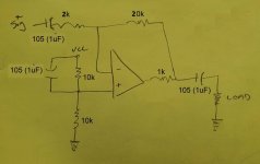
This is the schematic that I’ll be using:
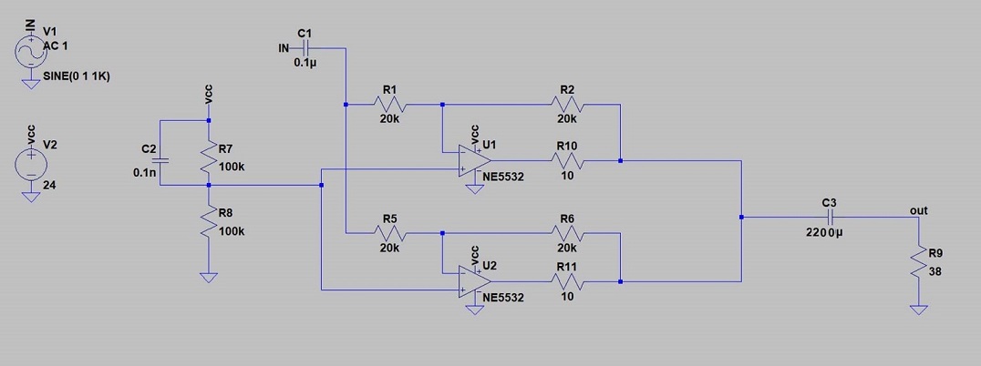
To start with, the Ebay boards are set to provide gain, but I require a unity gain buffer. So let’s set both the R1 and Rf both to 20k. This should provide enough impedance for the Korg to drive.
Next, a single NE5532 in stereo mode won’t provide enough current to run a pair of 38Ohm headphones, so I’m going to double up the boards. It seemed like the simplest option would be to mount the boards back-to-back and use one board per channel (rather than paralleling the board channels side to side).
To parallel the boards, it is necessary to place a balancing resistor at the output to stop the opamps fighting each other, so I removed the 1k resistors that were at the outputs and replaced these with 10R 1% resistors.
I changed out the input caps with 0.1uF MLCCs and used 2200uF for the output cap. None of the caps are particularly special or good quality, but better than what was preinstalled. I did leave a 0.1uF cap ‘bypassing’ the output cap, but I don’t see that it contributes anything. The tracks were starting to get fragile, so I opted to leave it alone rather than attempt to remove it.
I joined the L and R channels together and used just one signal coupling cap and one output cap per channel. Boards were mounted to each other using plastic standoffs and the back of the power supply pins on one board were jumpered across to the other with tinned solid wire.

Bench Testing
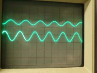
A 24v Bench supply was connected and the amp was fed with a 1kHz sine wave. The output looked fine and so I connected it up to sacrificial headphones with a mobile phone as source.
Using a tone generator, I could tell that the bass starts to roll off a bit under 200Hz, which is what I was seeing in the sim. This appears to be down to the values of the feedback resistor, output capacitor and the headphone impedance forming a High Pass filter, which I’ll play with at a later time.
Thermal performance was good – the SS_V6s heated quickly but only got to around 30-35 degrees (Celsius) after an hour inside a closed plastic box.
Listening
I listened to the amp through Audio Technika M50X headphones connected to the Korg and a Hifiberry DAC / Raspberry Pi running Volumio switching between the NE5532 and the SS_V6 multiple times.
Comparing bare Korg B1 to Korg B1 + NE5532, I found the sound to still be similar in tone and ‘warmth’ (or H2 distortion pleasantness), but with better detail. There was less bass response due to factors already mentioned but overall, the frequency range was satisfactory enough for headphone listening.
Moving on to NE5532 versus SS_V6, I found that there was little difference in volume when changing the chips over. There was better channel separation – when sounds swept from left to right, it sounded more spacious with the SS; more refined. I feared that adding the buffer to the Korg would be like putting tomato sauce on caviar, but I’m satisfied that the buffer isn’t detrimental to the sound of the Korg.
Being what some describe as an ‘effects generator’, I decided that the Korg B1 was flavouring the sound too much to make a useful comparison, so I moved on to testing the buffer in a few different configurations - straight from my mobile phone; straight from my laptop; and from laptop connected with DragonFly Red DAC. The laptop needed to be on battery power as I found that its power brick was causing an awful ground loop / 50Hz buzz. I’ll need to fix that up later, but for now battery power works.
Overall, I found that the NE5532s were acceptable but bland, particularly when paired with the DragonFly. There was a lack of body or depth to the sounds and it was ‘ok but ordinary’. The SS_V6 I found to be richer and definitely more detailed. For example, on Gotye’s ‘Someone I used to know’, I could hear the tremble of the drum skin, and on his track ‘State of the Art’, I could discern an additional voice mingled in with the vocoder – something that I had never heard before, even though I use those tracks extensively when testing. On ‘Hey Brother’ by Avicii (RIP Tim), I could hear two distinct voices in the call/response section of the song that I had always heard as one voice.
I found the instrument separation to sound a little over the top sometimes. For example, Lionel Richie’s ‘Hello’ has an acoustic guitar playing on the left side, but it sounded more distinct than the rest of the music and a little distracting. If you take members of a band playing and space them far enough apart, at some point they will no longer sound like a band but individuals playing at the same time. I felt that the amp was reaching that distance threshold at times.
The SS definitely sounded less clinical than the NE5532, but it didn’t colour the sound as significantly as the Korg does. It had a lighter touch but not enough to call ‘warmth’.
I gave the buffer a workout with ‘Put it’ by Schlohmo and the SS had a better response range. I found the NE5532s to be a bit ‘shouty’ at the upper frequencies and the SS a bit softer but not mushy. I could listen to a couple of Adele tracks without getting too annoyed at her vocal pitch with the SS.
Final Thoughts
I was sceptical that there would be any difference between the NE5532 and the SS_V6. My bias was towards there being no, or little, discernible difference and that all of the flowery words and bar graphs were just utter bo**ocks. Sure, I didn’t hear that ‘a veil had suddenly been lifted’, and my wife definitely didn’t ask what I had changed, as the typical clichés go - but I did hear a difference. I could hear a different level of quality to the sound, and I really didn’t expect that.
Do I think people should be pulling opamps out of their stereo equipment and jamming something different in with no consideration or respect to the original circuit design? The engineer in me is repulsed by even the suggestion. But hey, with wide compatibility, reverse voltage protection (on the V6) and lifetime warranty, what’s the worst that can happen by giving it a fair dinkum go...? You might be pleasantly surprised by the difference, or at least enjoy the pursuit.
Next Project
Not content with playing with the Bursons for just this project, I’ve got a cheap NE5532 + TDA 7265 board on its way. I want to see if a decidedly average amp can be made to sound much less average with a few simple component changes and a couple of Supreme Sounds.
Thanks for reading!
A few of points of preamble. I am just an ordinary DIYer. Anything presented in the thread is how I did things but does not constitute a recommendation for how you should do things. If anything here causes you to burn your house down, electrocute the cat, whatever – that is your responsibility and problem.
Secondly, you might copy everything I did but it may sound rubbish to you. Or it might sound better. I don’t have ‘golden ears’ or claim to have any special ability when it comes to listening – my hearing rolls off at 13 and 15kHz thanks to a love of Jet engines..
Third, I don’t currently have access to any special testing equipment other than a signal generator and a CRO. I can see gross errors like oscillation and bad waveforms, but I cannot perform THD tests etc. This means that the following will be subjective, not scientific. I’d love nothing more than to compare graphs and figures, but sadly this is going to be a listening and enjoyment exercise with as few clichés as I can stomach (no veils will be lifted in the making of this project 😉).
Lastly, I have no affiliation, affinity etc to Burson other than they sent me a product to play with and asked for my thoughts. I’ve received no payment or benefit other than being able to keep the product.
Delivery
The package took around a month to arrive from Hong Kong. Inside the little Jiffy bag was the product and a couple of zip ties. Not sure what those are intended for, but thanks anyway.
The product comes in a small, hard plastic case with a nice dense foam insert, cut out to fit the opamps snugly. Beneath the foam was a card with a couple of ‘Q’ codes that take you to the product information page on their website.
The first thing that struck me with the product was the logo that it bears. Hmm I’m sure I’ve seen that one before somewhere….
Project
The initial project I chose was to create an inverting buffer to couple with my Korg B1 Buffer (which I use as a headphone amp). The Korg inverts the signal phase and apparently negative H2 distortion is not as nice as positive H2 for some people. When used as a preamp, correcting this is a simple case of switching the speaker lead + and - over, but it’s not so easy when using headphones. I don’t fancy rewiring mine, so a simple NE5532 buffer in inverting configuration is the way I’ll go.
In preparation, I chucked a DC power jack onto the back of the Korg. I am using the PCB from Algar_Emi (GB B1 Nutube PCB with integrated PS) that is equipped with a Meanwell IRM-20-24 900mA power supply that I tapped after the first stage of filtering. The Korg only draws around 60mA or so, so plenty of power left for a couple of NE5532s.
Donor Boards
First thing to do was order some cheap ebay NE5532 boards that will suit the task. I chose a single ended supply version with through-hole components for ease of modification, and so that I can piggy-back the 24v power supply off the Korg (rather than needing to create a split supply).
A pack of 5 pre-populated boards set me back $14AUD delivered (or less than $10USD).
Schematic
I roughly traced out the schematic from the Ebay board. The capacitor values were higher than expected – 1uF as opposed to 0.1uF from the datasheet. The board is set up as a preamp with a gain of -10 set by way of 2k/20k resistors. There is a 1k at the output of the opamp. As this is a single ended supply, the amp has been biased with a voltage divider at the non-inverting input using 10k resistors – I was expecting 100k in this position, but this seems to work.
Modifications
This is the schematic that I’ll be using:
To start with, the Ebay boards are set to provide gain, but I require a unity gain buffer. So let’s set both the R1 and Rf both to 20k. This should provide enough impedance for the Korg to drive.
Next, a single NE5532 in stereo mode won’t provide enough current to run a pair of 38Ohm headphones, so I’m going to double up the boards. It seemed like the simplest option would be to mount the boards back-to-back and use one board per channel (rather than paralleling the board channels side to side).
To parallel the boards, it is necessary to place a balancing resistor at the output to stop the opamps fighting each other, so I removed the 1k resistors that were at the outputs and replaced these with 10R 1% resistors.
I changed out the input caps with 0.1uF MLCCs and used 2200uF for the output cap. None of the caps are particularly special or good quality, but better than what was preinstalled. I did leave a 0.1uF cap ‘bypassing’ the output cap, but I don’t see that it contributes anything. The tracks were starting to get fragile, so I opted to leave it alone rather than attempt to remove it.
I joined the L and R channels together and used just one signal coupling cap and one output cap per channel. Boards were mounted to each other using plastic standoffs and the back of the power supply pins on one board were jumpered across to the other with tinned solid wire.
Bench Testing
A 24v Bench supply was connected and the amp was fed with a 1kHz sine wave. The output looked fine and so I connected it up to sacrificial headphones with a mobile phone as source.
Using a tone generator, I could tell that the bass starts to roll off a bit under 200Hz, which is what I was seeing in the sim. This appears to be down to the values of the feedback resistor, output capacitor and the headphone impedance forming a High Pass filter, which I’ll play with at a later time.
Thermal performance was good – the SS_V6s heated quickly but only got to around 30-35 degrees (Celsius) after an hour inside a closed plastic box.
Listening
I listened to the amp through Audio Technika M50X headphones connected to the Korg and a Hifiberry DAC / Raspberry Pi running Volumio switching between the NE5532 and the SS_V6 multiple times.
Comparing bare Korg B1 to Korg B1 + NE5532, I found the sound to still be similar in tone and ‘warmth’ (or H2 distortion pleasantness), but with better detail. There was less bass response due to factors already mentioned but overall, the frequency range was satisfactory enough for headphone listening.
Moving on to NE5532 versus SS_V6, I found that there was little difference in volume when changing the chips over. There was better channel separation – when sounds swept from left to right, it sounded more spacious with the SS; more refined. I feared that adding the buffer to the Korg would be like putting tomato sauce on caviar, but I’m satisfied that the buffer isn’t detrimental to the sound of the Korg.
Being what some describe as an ‘effects generator’, I decided that the Korg B1 was flavouring the sound too much to make a useful comparison, so I moved on to testing the buffer in a few different configurations - straight from my mobile phone; straight from my laptop; and from laptop connected with DragonFly Red DAC. The laptop needed to be on battery power as I found that its power brick was causing an awful ground loop / 50Hz buzz. I’ll need to fix that up later, but for now battery power works.
Overall, I found that the NE5532s were acceptable but bland, particularly when paired with the DragonFly. There was a lack of body or depth to the sounds and it was ‘ok but ordinary’. The SS_V6 I found to be richer and definitely more detailed. For example, on Gotye’s ‘Someone I used to know’, I could hear the tremble of the drum skin, and on his track ‘State of the Art’, I could discern an additional voice mingled in with the vocoder – something that I had never heard before, even though I use those tracks extensively when testing. On ‘Hey Brother’ by Avicii (RIP Tim), I could hear two distinct voices in the call/response section of the song that I had always heard as one voice.
I found the instrument separation to sound a little over the top sometimes. For example, Lionel Richie’s ‘Hello’ has an acoustic guitar playing on the left side, but it sounded more distinct than the rest of the music and a little distracting. If you take members of a band playing and space them far enough apart, at some point they will no longer sound like a band but individuals playing at the same time. I felt that the amp was reaching that distance threshold at times.
The SS definitely sounded less clinical than the NE5532, but it didn’t colour the sound as significantly as the Korg does. It had a lighter touch but not enough to call ‘warmth’.
I gave the buffer a workout with ‘Put it’ by Schlohmo and the SS had a better response range. I found the NE5532s to be a bit ‘shouty’ at the upper frequencies and the SS a bit softer but not mushy. I could listen to a couple of Adele tracks without getting too annoyed at her vocal pitch with the SS.
Final Thoughts
I was sceptical that there would be any difference between the NE5532 and the SS_V6. My bias was towards there being no, or little, discernible difference and that all of the flowery words and bar graphs were just utter bo**ocks. Sure, I didn’t hear that ‘a veil had suddenly been lifted’, and my wife definitely didn’t ask what I had changed, as the typical clichés go - but I did hear a difference. I could hear a different level of quality to the sound, and I really didn’t expect that.
Do I think people should be pulling opamps out of their stereo equipment and jamming something different in with no consideration or respect to the original circuit design? The engineer in me is repulsed by even the suggestion. But hey, with wide compatibility, reverse voltage protection (on the V6) and lifetime warranty, what’s the worst that can happen by giving it a fair dinkum go...? You might be pleasantly surprised by the difference, or at least enjoy the pursuit.
Next Project
Not content with playing with the Bursons for just this project, I’ve got a cheap NE5532 + TDA 7265 board on its way. I want to see if a decidedly average amp can be made to sound much less average with a few simple component changes and a couple of Supreme Sounds.
Thanks for reading!
Attachments
-
 EbayTop.jpg111.6 KB · Views: 546
 -
 Sim.jpg106.3 KB · Views: 512
 -
 ScopeOut.jpg97.5 KB · Views: 533
 -
 Product 1.jpg82.3 KB · Views: 533
 -
 Korg.jpg79.1 KB · Views: 536
 -
 Final Cap.jpg142.1 KB · Views: 510
 -
 Final Burson.jpg87.2 KB · Views: 517
 -
 logo.jpg79.6 KB · Views: 545
 -
 Schematic.jpg78.6 KB · Views: 511
 -
 SchemeEbay2.jpg174.4 KB · Views: 510
Last edited:
Interesting comparison, cool project too. That is just about what I had noticed comparing those parts to the ne5532 also.
I had assumed the zip ties were provided to aid in the removal of the dip-8 parts from their sockets, a nice touch.
I had assumed the zip ties were provided to aid in the removal of the dip-8 parts from their sockets, a nice touch.
Interesting comparison, is just about what I had noticed comparing those parts to the ne5532 also.
I had assumed the zip ties were provided to aid in the removal of the dip-8 parts from their sockets, a nice touch.
I had assumed the zip ties were provided to aid in the removal of the dip-8 parts from their sockets, a nice touch.
True, they could be useful for the removal of the existing ICs if you don't have a proper tool.
Perhaps a cheap removal tool could have been included to make it a full kit for those that want to play around with their systems but don't necessarily have tools available.
Perhaps a cheap removal tool could have been included to make it a full kit for those that want to play around with their systems but don't necessarily have tools available.
Your schematic shows the virtual ground being decoupled to Vcc, not ground, so that you directly inject rail noise into the input.
Whoops.
And C1 should be more like 2µ2 to avoid losing deep basss.
Whoops.
And C1 should be more like 2µ2 to avoid losing deep basss.
Good spot, Mark. I'll have to check if it is physically connected that way or just got drawn the wrong way in the schematic diagram.
And thanks for the tip on C1. I was running sims last night with C1 at 1uF which gave me a roll off at around 16Hz iirc. But I'll pop 2.2 there instead and see how it sounds.
Thanks again, this is my first foray into opamps so I appreciate the clues to keep me on track.
And thanks for the tip on C1. I was running sims last night with C1 at 1uF which gave me a roll off at around 16Hz iirc. But I'll pop 2.2 there instead and see how it sounds.
Thanks again, this is my first foray into opamps so I appreciate the clues to keep me on track.
Last edited:
I wonder if it would be worthwhile to place a cap over the feedback resistor to for a low pass filter also - cut the HF that is.
2.2uF caps now installed in the input cap position, and the bass response is much better now. Significantly better.
Santa came early and dropped off a Focusrite 2i4 so that I can finally carry out some distortion measurements.
The following measurements were taken with no changes to the test leads (except loopback, obviously) and unchanged local environmental conditions.
The setup was a laptop running on battery power, focusrite 2i4 and 6dB attenuator (input protection).
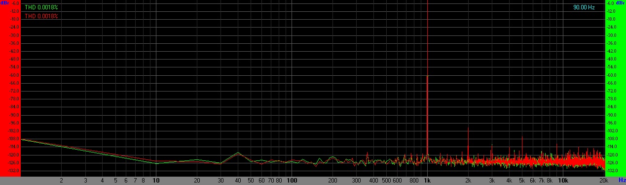
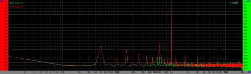
So starting with the pre-calibrated loopback, we have distortion around 0.0018% and a noise floor of around -120dB:
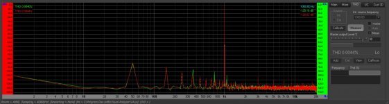
Post calibration with the NE5532s we have similar noise floor, 0.0040% THD with dominant H3:
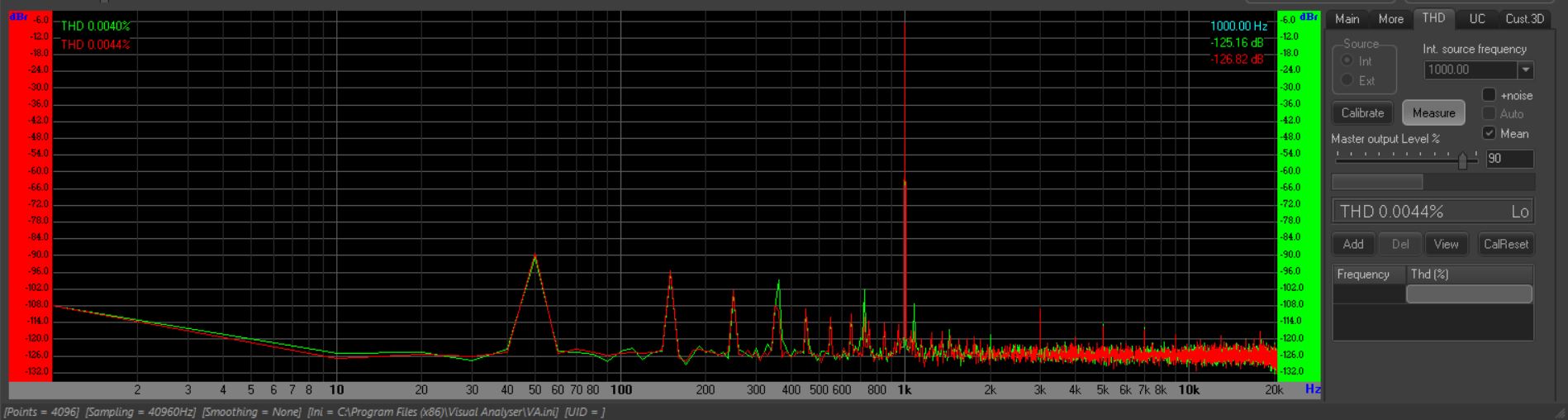
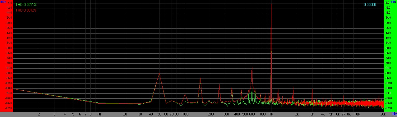
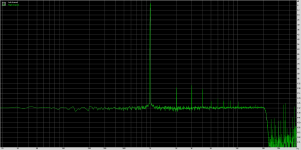
And with the Bursons, we have (maybe?) dominant H2 (or is it noise as it is under 2kHz?), THD at 0.0011% with a strange 600Hz peak on one channel.
I'm new to making measurements with the focusrite (this is literally my first go), but I thought I'd share some data anyway.
Santa came early and dropped off a Focusrite 2i4 so that I can finally carry out some distortion measurements.
The following measurements were taken with no changes to the test leads (except loopback, obviously) and unchanged local environmental conditions.
The setup was a laptop running on battery power, focusrite 2i4 and 6dB attenuator (input protection).
So starting with the pre-calibrated loopback, we have distortion around 0.0018% and a noise floor of around -120dB:
Post calibration with the NE5532s we have similar noise floor, 0.0040% THD with dominant H3:
And with the Bursons, we have (maybe?) dominant H2 (or is it noise as it is under 2kHz?), THD at 0.0011% with a strange 600Hz peak on one channel.
I'm new to making measurements with the focusrite (this is literally my first go), but I thought I'd share some data anyway.
Attachments

Looking at the peaks they don't seem to match the calculated THD values.
For the NE5532 H2 and H3 seem to be -112 and -104 dB down on the -6dB signal level, which is 0.00068% (ignoring higher harmonics)
and the Burson the peak for H3 is -102dB down from the signal, ie 0.0008%. You have confused a spur at 1.8kHz for H2. That is likely the 3rd harmonic of the strange 600Hz signal.
The wide base of the 600Hz signal signals high phase noise, indicating its a free-running oscillation of some sort, not derived from a quartz crystal timebase. Alternatively that spread of the peak might be due to using an inappropriate FFT window with spectral leakage.
Last edited:
I suspected the peak at 1.8kHz was from something else.
Today I had a go with RMAA to see if it makes a difference.
Here is the loopback:

As you can see, there is no 600Hz bump and 50Hz filtering is good.
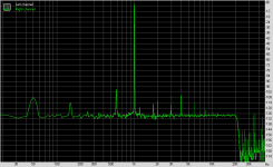
Next is a single channel run with the Burson installed:

RMAA puts THD at 0.00124% on this run.
Note the 600Hz peak is there again although it actually measured on RMAA at 550-570Hz. When measuring both channels, the RH channel was considerably noisier than the LH. Something else to investigate.
The 600Hz might be coming from the fairly cheap SMPS (which is passing quite high 50Hz noise). I'll have to run the tests again with a different supply when I get a chance.
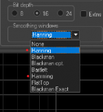
I believe I had Hanning selected for this one.
Today I had a go with RMAA to see if it makes a difference.
Here is the loopback:
As you can see, there is no 600Hz bump and 50Hz filtering is good.
Next is a single channel run with the Burson installed:
RMAA puts THD at 0.00124% on this run.
Note the 600Hz peak is there again although it actually measured on RMAA at 550-570Hz. When measuring both channels, the RH channel was considerably noisier than the LH. Something else to investigate.
The 600Hz might be coming from the fairly cheap SMPS (which is passing quite high 50Hz noise). I'll have to run the tests again with a different supply when I get a chance.
Alternatively that spread of the peak might be due to using an inappropriate FFT window with spectral leakage.
I believe I had Hanning selected for this one.
Attachments
OK the Hann window (named after Julius von Hann) has fairly good spectral properties. Its not highly accurate for peak-height though, expect upto -1.4dB peak height error if signal frequency doesn't divide FFT rate.
People get confused by the Hamming window (Richard Hamming as in Hamming distance), and rename Hann as Hanning!
If you want exact peak heights there are flat-top windows available.
For noise floor measurements Hann window is a good choice BTW.
People get confused by the Hamming window (Richard Hamming as in Hamming distance), and rename Hann as Hanning!
If you want exact peak heights there are flat-top windows available.
For noise floor measurements Hann window is a good choice BTW.
People get confused by the Hamming window (Richard Hamming as in Hamming distance), and rename Hann as Hanning!
Seems the creator of Visual Analyser was confused too!
Attachments
Whilst I await parts for the second project, I thought I would refine the first project into something a little more stable.
In the space of a couple of hours, I installed EasyEDA and fumbled my way around until I created my first from-scratch PCB design. Needless to say, it won't be the best layout or the most professional (or even work!), but I'm gonna have fun anyway.
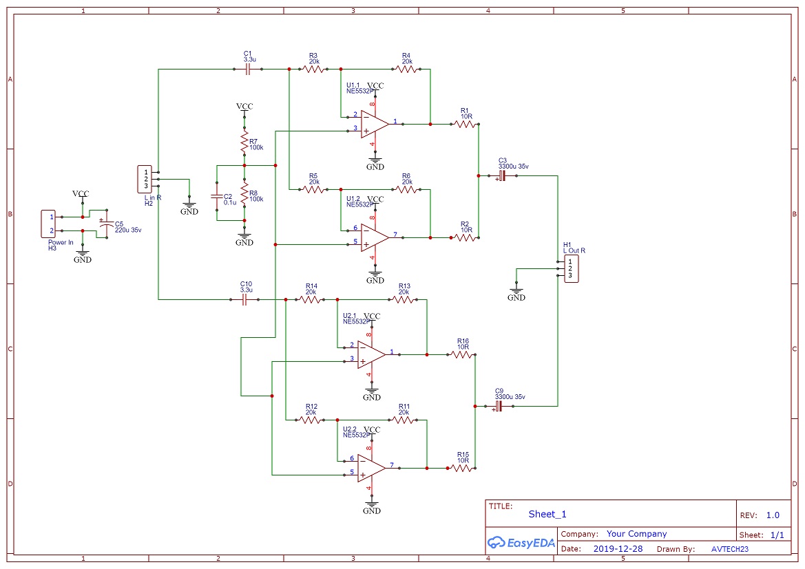
Just a reminder, this is an inverting, unity gain buffer using 2x NE5532 in parallel to boost current handling. The change in this version is that the parallel happens within each chip instead of half one chip parallel with half the other chip - i.e. now it is one chip dedicated per channel.
I'm using this schematic (similar to the earlier final scheme minus the 'whoops' - thanks Mark!):
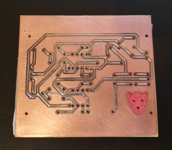
Once I came up with a single-sided layout that didn't require extra jumpers, I went about milling the board. (I have an old bottle of FeCl3 but I don't have a laser printer at home to do a transfer..!)
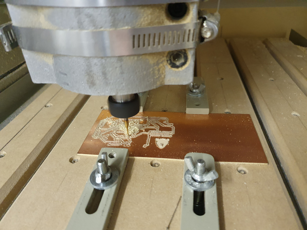
I chose 1mm tracks to make the board machinable, but it still took some fine tuning to get right. The copper layer is only 0.035mm thick, but the PCB itself deviates by perhaps 0.3mm across the height. This means that the cut was a little deeper than perhaps ideal, but nonetheless, it came out ok (for a first attempt).
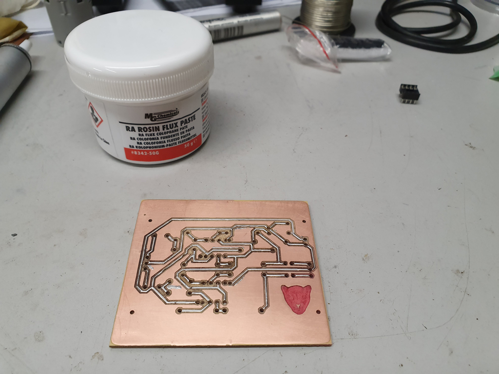
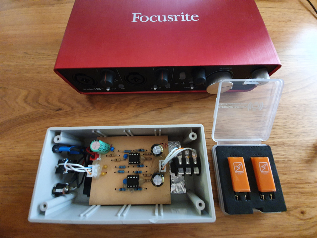
Once chopped to size and tinned, it was time to stuff. (BTW, good flux makes tinning the tracks so much easier).
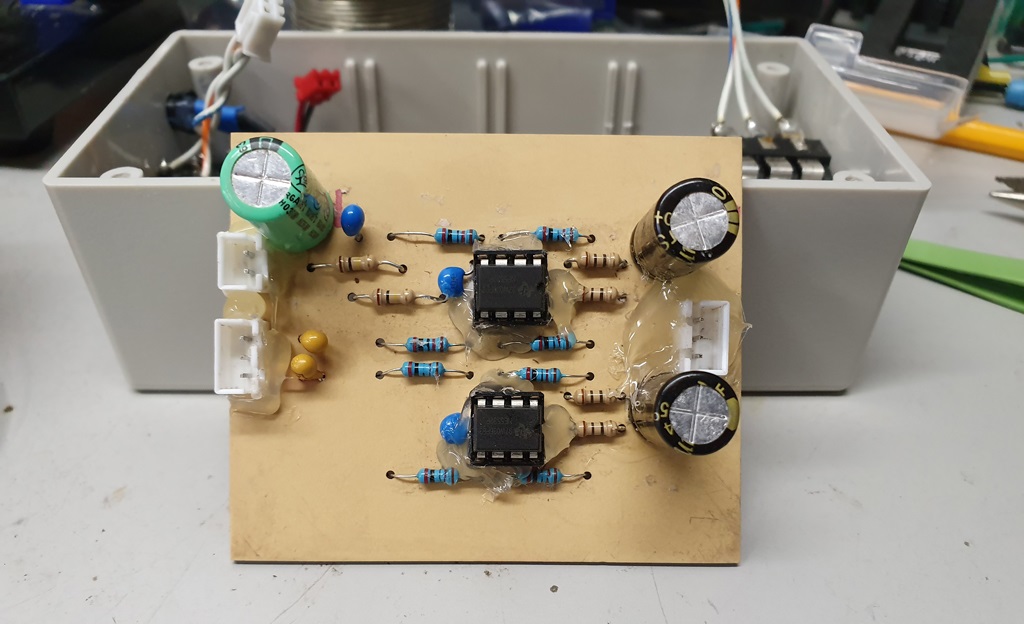
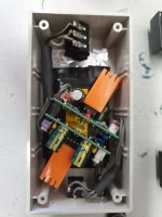
Installation of components was fairly straightforward with a little care needed due to the lack of pads and vias. Hot-snot glue provided the mechanical fixing for the connectors.
And yes, I did use tants for the input coupling caps. (I didn't have any appropriately sized PPs).
Once it was assembled and put in the existing case, it was time for the first turn-on test.
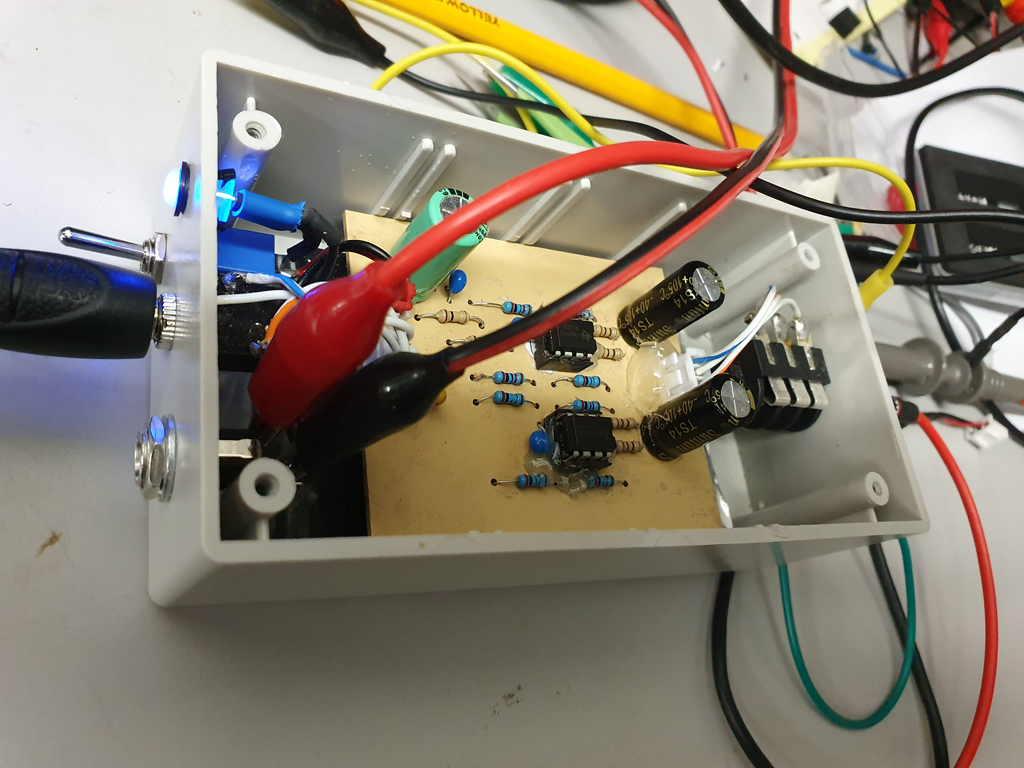
It actually works!
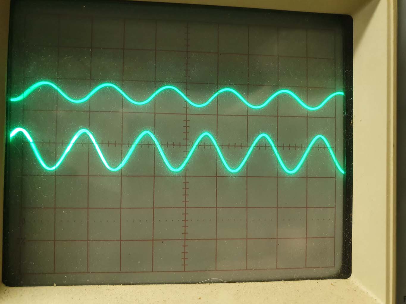
Hooked up to a 1kHz sine generator and the oscilloscope, the amp looked like this on each channel:
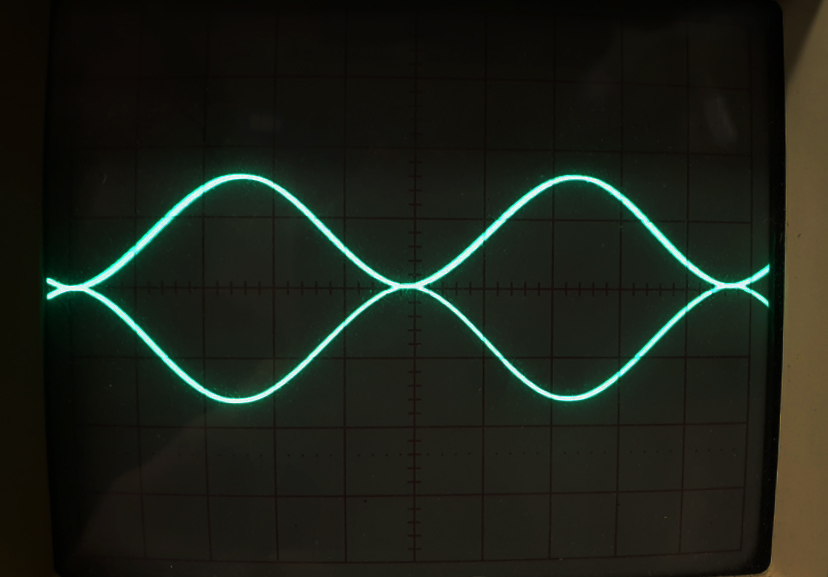
Time to hook it up to the test rig and see how it performs:
So for the NE5532 I got:
THD: LH = 0.00108% , RH = 0.00121%
THD + n: LH = 0.08697% , RH = 0.08468%
THD + n (A): LH = 0.05716% , RH = 0.05569%
Noise: -71dBA
Cross-talk: -74.9dB
For the Burson:
THD: LH = 0.00107% , RH = 0.00116%
THD + n: LH = 0.16568% , RH = 0.16120%
THD + n (A): LH = 0.06512% , RH = 0.06333%
Noise: -69.9dBA
Cross-talk: -69.5dB
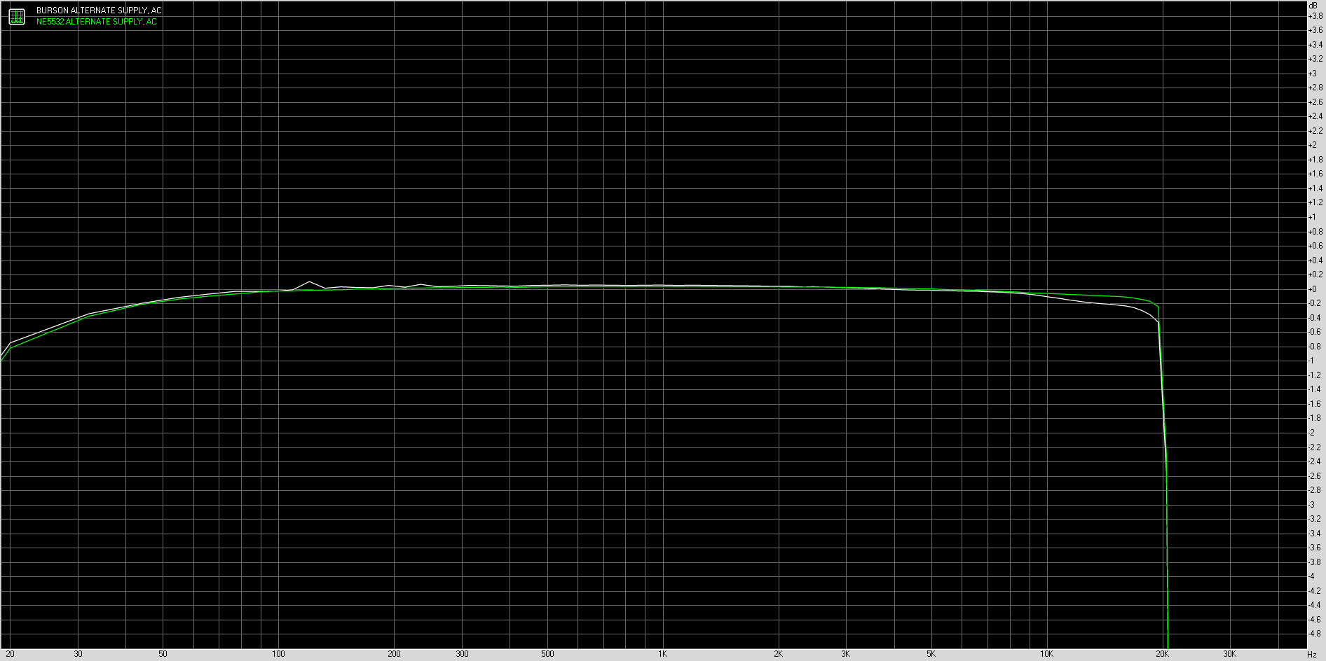
And the THD graph: (No idea what is happening to the Bursons at low frequency, but doesn't look good).
And a reasonable frequency response curve:
How does it sound?
Well as before, it sounds fairly plain and lacking with the standard NE5532 in circuit compared to the Bursons. There is more noise evident in this iteration which probably has a lot to do with my layout. The ~600Hz hum seems to have moved a bit lower in the NE5532 and is less obvious to my ears, but still there. Not enough to discern once the music plays. The ground loop problem* that plagued the ebay boards is resolved. This one has a pretty substantial turn on/off thump that I'll need to address.
(* The ebay boards had awful hum when driven by a plugged in, grounded laptop - even though the amp runs from a double insulated SMPS).
Anyway, I had some fun designing a PCB layout and milling my first PCB and all the issues that comes with it, so I thought I'd share.
In the space of a couple of hours, I installed EasyEDA and fumbled my way around until I created my first from-scratch PCB design. Needless to say, it won't be the best layout or the most professional (or even work!), but I'm gonna have fun anyway.
Just a reminder, this is an inverting, unity gain buffer using 2x NE5532 in parallel to boost current handling. The change in this version is that the parallel happens within each chip instead of half one chip parallel with half the other chip - i.e. now it is one chip dedicated per channel.
I'm using this schematic (similar to the earlier final scheme minus the 'whoops' - thanks Mark!):
Once I came up with a single-sided layout that didn't require extra jumpers, I went about milling the board. (I have an old bottle of FeCl3 but I don't have a laser printer at home to do a transfer..!)
I chose 1mm tracks to make the board machinable, but it still took some fine tuning to get right. The copper layer is only 0.035mm thick, but the PCB itself deviates by perhaps 0.3mm across the height. This means that the cut was a little deeper than perhaps ideal, but nonetheless, it came out ok (for a first attempt).
Once chopped to size and tinned, it was time to stuff. (BTW, good flux makes tinning the tracks so much easier).
Installation of components was fairly straightforward with a little care needed due to the lack of pads and vias. Hot-snot glue provided the mechanical fixing for the connectors.
And yes, I did use tants for the input coupling caps. (I didn't have any appropriately sized PPs).
Once it was assembled and put in the existing case, it was time for the first turn-on test.
It actually works!
Hooked up to a 1kHz sine generator and the oscilloscope, the amp looked like this on each channel:
Time to hook it up to the test rig and see how it performs:
So for the NE5532 I got:
THD: LH = 0.00108% , RH = 0.00121%
THD + n: LH = 0.08697% , RH = 0.08468%
THD + n (A): LH = 0.05716% , RH = 0.05569%
Noise: -71dBA
Cross-talk: -74.9dB
For the Burson:
THD: LH = 0.00107% , RH = 0.00116%
THD + n: LH = 0.16568% , RH = 0.16120%
THD + n (A): LH = 0.06512% , RH = 0.06333%
Noise: -69.9dBA
Cross-talk: -69.5dB
And the THD graph: (No idea what is happening to the Bursons at low frequency, but doesn't look good).
And a reasonable frequency response curve:
How does it sound?
Well as before, it sounds fairly plain and lacking with the standard NE5532 in circuit compared to the Bursons. There is more noise evident in this iteration which probably has a lot to do with my layout. The ~600Hz hum seems to have moved a bit lower in the NE5532 and is less obvious to my ears, but still there. Not enough to discern once the music plays. The ground loop problem* that plagued the ebay boards is resolved. This one has a pretty substantial turn on/off thump that I'll need to address.
(* The ebay boards had awful hum when driven by a plugged in, grounded laptop - even though the amp runs from a double insulated SMPS).
Anyway, I had some fun designing a PCB layout and milling my first PCB and all the issues that comes with it, so I thought I'd share.
Last edited:
Great data collection. Can you repeat the measurements with 10k in series with the signal generator, which will potentially highlight issues with current noise? Also do you know how much of the noise is due to the generator? Is it 50 ohm or 600 ohm output impedance?
Until you do double-blind listening tests any subjective reports I ignore because I know how strong expectation bias is.
BTW can't seem to get the image links to work there...
Until you do double-blind listening tests any subjective reports I ignore because I know how strong expectation bias is.
BTW can't seem to get the image links to work there...
BTW can't seem to get the image links to work there...
They should work now.
Great data collection. Can you repeat the measurements with 10k in series with the signal generator, which will potentially highlight issues with current noise? Also do you know how much of the noise is due to the generator? Is it 50 ohm or 600 ohm output impedance?
I'm using the Focusrite 2i4 with RMAA so it should self calibrate.
I do have an update r.e. noise, that I'll try post over the weekend (lots more pics, hopefully they'll work this time!)
Until you do double-blind listening tests any subjective reports I ignore because I know how strong expectation bias is.
I totally understand. I mostly skip through the listening tests myself - especially the part where the 'wife came in and asked where the veil had gone'... 😀
I do see utility in using the ears as a measuring device too though. An amp may measure great but sound 'off'. And if it doesn't sound good, then listening is not going to be an enjoyable experience, which is ultimately the goal.
But I certainly agree that without double blind testing, there are many bias traps to fall into.
Anyway back to the measurements, I still have noise at the ~500Hz region that I'm not sure what the source could be. It appears more with the 5532 than the Bursons. I have changed the SMPS with a 'proper' genuine (non-ebay) one, but that didn't make much difference. It does not appear on the loopback so it apparently isn't the laptop, 2i4 or leads. It was prevalent in the China boards as well as my own design.
Perhaps if you forgot to measure all the important things - there are a lot of them. Just assuming THD at 1kHz is measuring an amp is lazy.An amp may measure great but sound 'off'.
A common weakness in class B amps is the bias point shifting substantially with thermal changes in the amp - if the bias is thrown out enough it will distort grossly, and most standard tests don't check for this explicitly. (It can happen after loud passages where the output device die temperature drops rapidly and the temperature-compensating device much more slowly.)
Another issue I've seen testing amps is that oscillation has a greater tendancy to start at the peaks of low frequency signals if its borderline, so a 1kHz test may miss it, as will a 50kHz square-wave test. I presume this is due to large DC current simultaneous with die temperature rise leading to higher base currents during the peak as the gain drops with current and temperature. There may be a significant startup time for borderline oscillations. The best way to check for this would be DC tests, alas impractical with most audio amps, failing that a full power 20Hz test is useful, monitored with an RF spectrum analyzer ideally.
Perhaps the way to think of this is a listening test might catch some things that are tedious to check for with equipment unless your setup for a screed of automated tests.
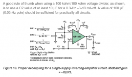
I finally got a chance to sit and read through the excellent Analog.com article: Avoid Common Problems When Designing Amplifier Circuits | Analog Devices which had a very good suggestion regarding supply decoupling:
Many of the examples online and textbooks suggest using 100nF decoupling at the voltage divider which mislead me.

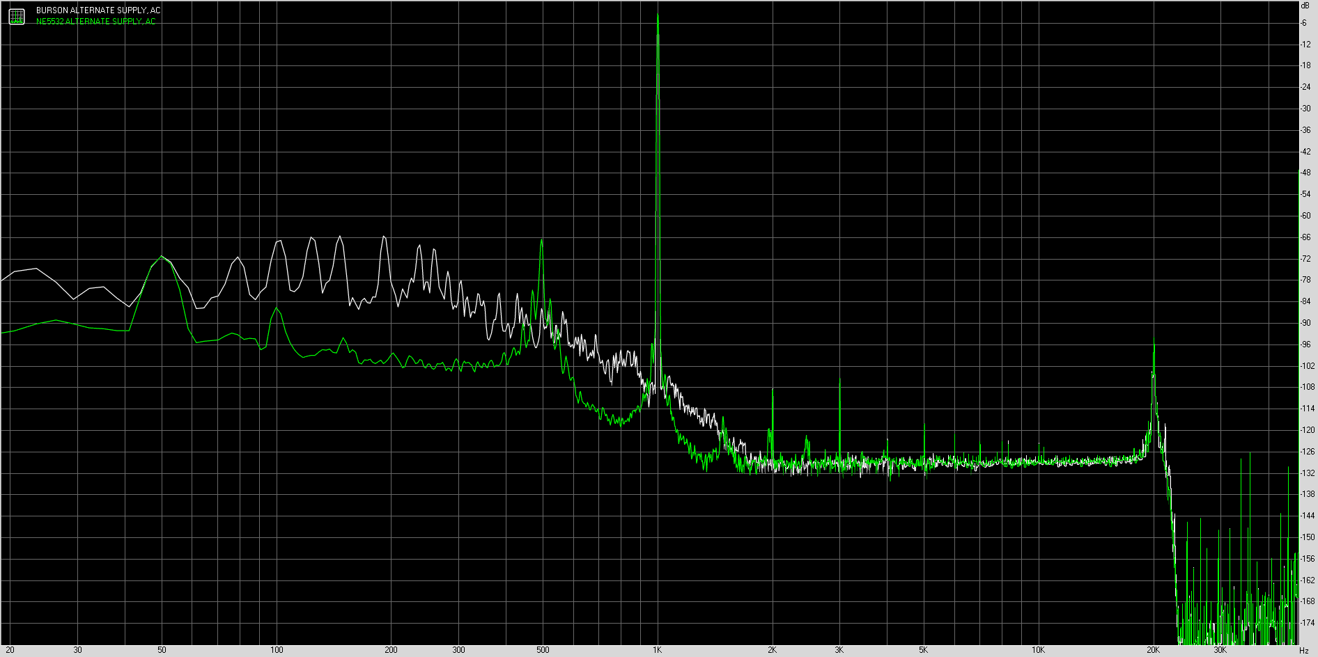
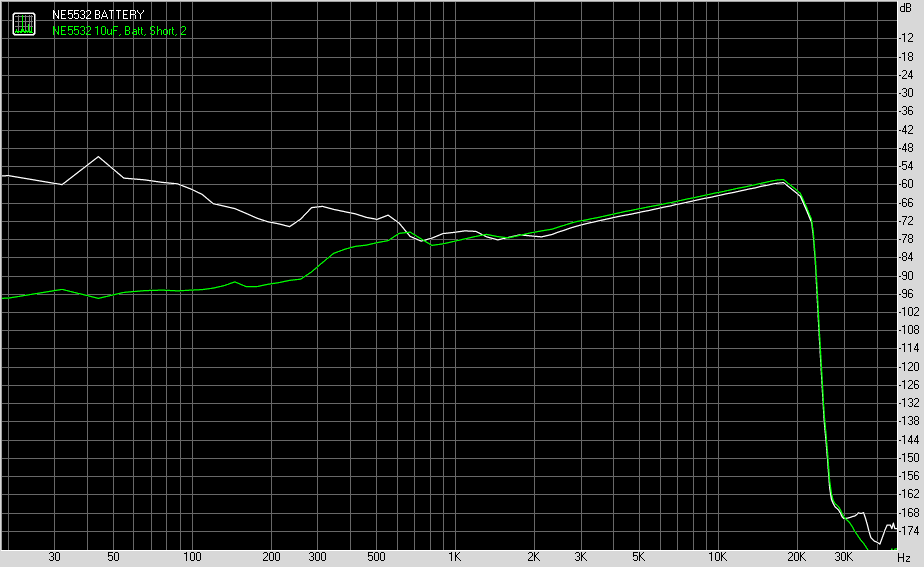
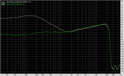
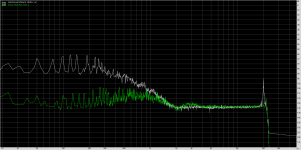
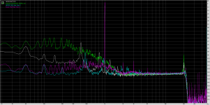
So I replaced the 100nF with a 10uF and the results are as follows:
(White is before, Green is after).
[Noise NE5532]
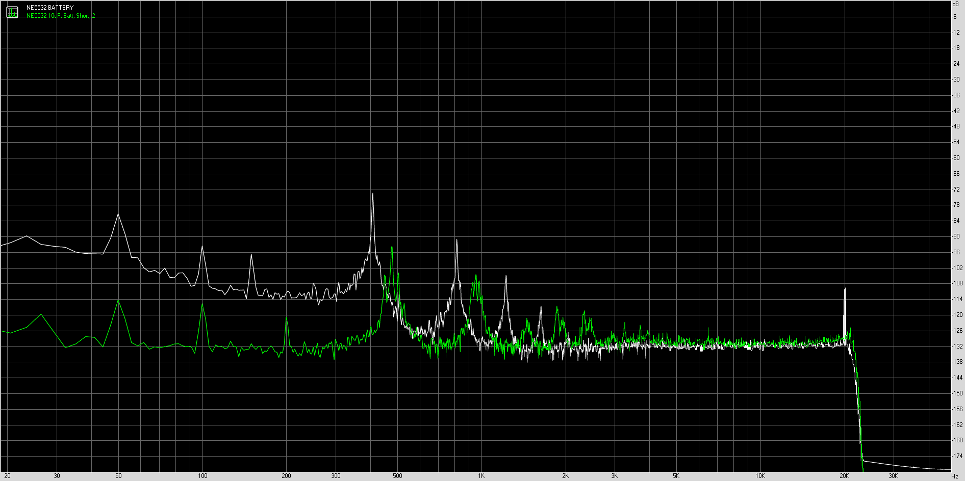
[Noise Burson]

[Crosstalk NE5532]
[Crosstalk Burson]
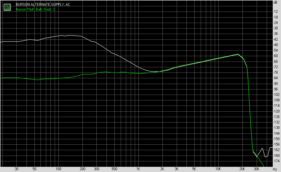
[Noise Overlay NE5532 and Burson]

The figures being:
NE5532 100n Noise -72.0dBA Crosstalk -75.7dB
NE5532 10uF Noise -91.3dBA Crosstalk -78.8dB
Burson 100n Noise -69.9dBA Crosstalk -69.5dB
Burson 10uF Noise -92.7dBA Crosstalk -78.8dB
As can be seen, using the correct value capacitor for the voltage divider bypass results in a marked change in the noise levels present in this circuit.
A common and incorrect practice is to use a 100-kohm/100-kohm resistor divider with a 0.1 μF bypass capacitor to supply VS/2 to the noninverting pin of the op amp. Using these values, power-supply decoupling is often inadequate, as the pole frequency is only 32 Hz. Circuit instability (“motor-boating”) often occurs, especially when driving inductive loads.
Many of the examples online and textbooks suggest using 100nF decoupling at the voltage divider which mislead me.
So I replaced the 100nF with a 10uF and the results are as follows:
(White is before, Green is after).
[Noise NE5532]
[Noise Burson]
[Crosstalk NE5532]
[Crosstalk Burson]
[Noise Overlay NE5532 and Burson]
The figures being:
NE5532 100n Noise -72.0dBA Crosstalk -75.7dB
NE5532 10uF Noise -91.3dBA Crosstalk -78.8dB
Burson 100n Noise -69.9dBA Crosstalk -69.5dB
Burson 10uF Noise -92.7dBA Crosstalk -78.8dB
As can be seen, using the correct value capacitor for the voltage divider bypass results in a marked change in the noise levels present in this circuit.
Attachments


Perhaps if you forgot to measure all the important things - there are a lot of them. Just assuming THD at 1kHz is measuring an amp is lazy.
If you were under time constraint, what would you consider to be the most crucial tests to run on a design to cover the most important indicators?
Odd that there's some 400Hz motor-boating with the NE5532? Something's up there. Perhaps the extra decoupling on the discrete opamp is changing the setup. Do you have the full schematic for the test-jig?
- Home
- Design & Build
- Parts
- My Burson Supreme Sound Projects