Sure, it keeps working nicely. It wasn't any original design, but based upon manufacturer datasheet recommendations.Yes, regiregi22. I hope you can join. Also, I took notes of the 5V PSU you made using C3-C8 to power your LDR. Is that still working out for you ?
Are you referring to RK168 series? As per datasheet, worst case condition is supplying 150mA at 6v, nearly 1 Watt. The regulator I used will work up to 1,5A and up to several watts if properly heatsinked. Keep in mind that it is a puntual consumption, thus changing volume is not a constant task (no quiescent current).Could it power a motorized Alps pot ?
In fact, I didn't finally mounted it inside the amp enclosure, but with a DCB1 in a separated preamp case, taking supply down to 5v from DCB1 PSU. How much current can you borrow? It will depend on power TX size, and how much ripple current will you allow to have on the LM3886. Asuming you're using BOM capacitors. But low current applicances should pose no problem.How much power could one leach from the My_Ref boards before the amp begins to suffer ?
Aren't you guys talking about the same? (powering LDR volume controls)"Also, I took notes of the 5V PSU you made using C3-C8 to power your LDR. Is that still working out for you ? Could it power a motorized Alps pot ? How much power could one leach from the My_Ref boards before the amp begins to suffer ?"
I have often wondered if such an arrangement could be used for the 5V needed on Uriah's Lightspeed.
Did you see my thread on my My_Ref derivate? It would be nice if you'll join the beta build. 😉
I will read the whole thread, and closely follow the development, it seems an interesting approach. But by the moment I am finishing an stereo BPA-300 (two channels, 12x LM3886), and still rest some work to do. After Building two standard gainclones, another one gainclone with regulated PSU, the My-Ref with U-BOM, a Nelson Pass' F5, and the current BPA-300, I think it's time to give a breath to the omnipresent LM3886 so.... maybe it's a good time to start with valve kits!Yes, regiregi22. I hope you can join.
Putting 12K in parallel with R7 proved to be very interesting. I am going to measure and see what I find.soongsc, why dont you vary the gain?
OriginaL MyRef C TP BOM
An externally hosted image should be here but it was not working when we last tested it.
MyRef C with Dario's compensation PMed to me.
An externally hosted image should be here but it was not working when we last tested it.
It seems the original has better frequency and phase response.
...
R7 cut to half
An externally hosted image should be here but it was not working when we last tested it.
Was there a specific reason why gm=1 for the original MyRef C design?
Last edited:
regiregi22,
Yea, same thing - I was just curious to know if anyone had successfully taken some power (5V) from the MyRef transformer to eliminate the wall wart/toroid for the Lightspeed in an integrated build. I wouldn't even consider it for the 12V for the Lighter Note. But apparently you took a different path.
Yea, same thing - I was just curious to know if anyone had successfully taken some power (5V) from the MyRef transformer to eliminate the wall wart/toroid for the Lightspeed in an integrated build. I wouldn't even consider it for the 12V for the Lighter Note. But apparently you took a different path.
I took a different path, but same procedure applies (DCB1 instead of My_Ref). I went even further than taking supply from the torroid. I took supply directly from the PSU smoothing caps, so you don't need to add another diode bridge neither smoothing caps before the regulator. The regulator just take down those +35vdc (but depends on your trafo voltage) to +5vdc.regiregi22,
Yea, same thing - I was just curious to know if anyone had successfully taken some power (5V) from the MyRef transformer to eliminate the wall wart/toroid for the Lightspeed in an integrated build. I wouldn't even consider it for the 12V for the Lighter Note. But apparently you took a different path.
Try it first without heatsinking the regulator, you are going to drop 25-30 volts, but due to the low current it has to supply, heat may not be an issue.
Regards,
I know this doesn't really have much to do with the My_Ref, theory wise but for those building a integrated amp and not have the chassis filled with tiny transformers; what regi did really interested me. I took some notes from this thread. the number after a users name is the post number of the Ultimate BOM thread so I could go back and read what I failed to copy to notepad.
We will tap the +35vdc from the already rectified and smoothed out from the My_RefC PSU. You can hook up a pair of wires to the solder side of the big 10.000uF caps, this is a clear/easy place to solder. These will give us around +35vdc, so we will step it down to +5vdc using an LM338 regulator. We could use the lower-current-rated LM317, but Uriah told me that LM338 is more stable, so no place for discussion with the small price difference they have. You can mount this circuit on a little piece of stripboard or veroboard. You can even mount it point-to-point if you have enough care.
Here are some technical explanations, not necessary to succesfully build the circuit:
-An output load resistor makes any regulator happier It keeps a constant load all the time, which turns out to give a better steady voltage. The LM338 datasheet says that it has a minimum load current ranging from 3.5 to 10mA, so a 500 Ohm resistor will suck 10mA. Plus the Lightspeed consumption, it will be enought current. R3 is using 50mW, so a 1/4W resistor will suffice.
-R1 is 100 Ohm to allow pass a 12.5mA adjustment pin current. Everywhere is recommended to put there at least 10mA. With 1.25v it consumes 15mW, so an 1/4W resistor is enough.
-R2 is 330 Ohm. I don't know how to calcule its consumption, but I know that you need a 1/2W resistor if you go above 1.6k having R1=100. SO we are fine with a 1/4W resistor.
...you could use the same value as R2 for R3. Should be perfect, even a bit better than 500 Ohm. 330Ohm will consume 75mW
-C1 and C3 are bypass caps, which improves regulator performance. C2 improves ripple rejection. C4 is there to provide some output capacitance and doing a bit of post-filtering, like C3. They have to be tantalum types (or even film types) because of its high-frecuency response.
The only one cap that needs to be 50v is C1. 35v would work, but too tight for long-term endurance. The others can be anything above 5v or 10v.
-D1 and D2 provide protection in case that the currents from capacitors return back and damage the regulator. 1N4002 or 1N4003 are enough.
-Uriah suggested me to use resistors with a low PPM. That means to have a low thermal drift. Output voltage will fluctuate less due thermal variations. But, in practice, with a more or less steady power consumption, this is not a big deal.
-I would go with metal film resistors because of its advantages, but it goes down to personal choice. For the load resistor R3, it is suitable to use something between 200 and 500 ohms aprox. The lower, the more consumption, and maybe the better regulation. 500 Ohms will consume 50mW (10mA), 200 will consume 125mW (25mA). For D1 and D2, you can use RS part nº 628-8953 (1N4002). There isn't any advantage in using 1N4003 (maximum 200v), as 1N4001 already support max 100v.
This circuit will provide you a first-class regulated +5vdc supply for your Lightspeed or anything else you want. You can even hook up a LED to ensure that it keeps working. The regulator will get a bit hot because of the big voltage drop, but not too much because of Lightspeed's low current consumption. You will have to attach it to an small heatsink, or to the same heatsink as the LM3886, but making sure that it's well insulated from it.
Building the Lightspeed attenuator with Uriah's matched LDRs should be trouble-free. It should take no more than a square inch veroboard. But with the supplied kits, boards are included. Hook it up to the regulated PSU and you're done. The PSU shouldn't take up more than an square inch board.
Mouser BoM for 5V regulator
R1: 71-RN55D-F-100
R2: 71-RN55D3300F
R3: 71-RN55D-F-499
C1, C3: 80-T356B105K050AT
C2: 80-T350G106K035AT
C4: 667-EEU-FC1V101
D1, D2: 512-1N4002
Pot: 313-2420F-100K
Mouser doesn't have the L338 in their stock, you could replace it with the LM317 without a hassle. It provides already more than 20x times the requiered power by the Lightspeed,and is as good as the LM338. Here is the part number: 512-LM317T
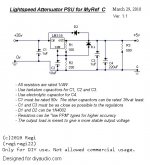
regi 514 :Well, I have finished the PSU I will be using to integrate the Lightspeed attenuator that Uriah kindly offered to us at a very reduced price in the kit.
I managed to fit it in...an square centimeter! It's amazing how small you can make a regulator. You just have to take +35v from any of the MyRef_C boards. Attached is the schematic.
It may seem a bit messy and filthy, but it works as a charm, steady and clean voltage. It has a very robust construction, and being light can be directly attached to a big heatsink and hold it just hanging. Blue wire is input, white wire is output ant the bare grey is ground.
Another thing I have finished are the GROUND BREAKING devices. I am very concerned about electrical security, so I REFUSE to keep untied protective earth and GND from the amp. Just imagine what will happen if the live from the mains hangs out and touch an RCA socket. You will have 220v on the RCA; not really my concept of security. Especially if you have kids around with their (sometimes) wet fingers and their unavoidable neccesity to touch everything they see.
I have used this little devices in other designs, and they work really well. Here in the link you have a technical explanation, but resuming it, the diodes will not conduct if voltage is not at least the diode breakdown voltage. So, in a non-failure situation, diodes will not conduct and the capacitor will allow to pass ONLY high frecuency interference, thus allowing the case to act as a RF shield. The resistor will mantain PE and ground tied, but reducing circulating currents caused by ground loops to a minimum.
In case of failure, like the example with the RCA, the diode bridge will allow high current faults to pass, thus tripping the breaker from the house electrical panel, and derivating those currents to earth. Earthing (Grounding) Your Hi-Fi - Tricks and Techniques
AndrewT 623 : For 5V from a 317:
a pair of LEDS totaling 3.7V to 3.8V substituted for R2 will give near enough the right voltage and will allow the 317 to perform better
Attachments
Last edited:
Based on current experiment and simulation, I instinct is that R7=4K R5&R8=47K might be an optimum solution. The only thing left to try myself is to get the 47K resistors with the tolerance required, will take a couple of days.R7 cut to half
An externally hosted image should be here but it was not working when we last tested it.
Was there a specific reason why gm=1 for the original MyRef C design?
Hi Soongsc,
Very interesting, it could be a easy upgrade to the amp. Please let us know how it sounds when you implement the change.
PJN
Very interesting, it could be a easy upgrade to the amp. Please let us know how it sounds when you implement the change.
PJN
That combination provides for the best frequency response and damping so far. Sonic coloration is much reduced. The gain is also reduced due to R7. Improvements also include better separation of instruments, and depth location difference. Background recorded room timbre is more evident. It's getting very close to my reference.
Some additional improvement might be possible with C4 change, I just need to confirm whether what I hear is related with this or not. But also bear in mind that I have a different power supply, so people interested still need to know that there is some uncertainty.
Some additional improvement might be possible with C4 change, I just need to confirm whether what I hear is related with this or not. But also bear in mind that I have a different power supply, so people interested still need to know that there is some uncertainty.
C4 changed to a 0.68uF X2 cap I had on hand, but the original TP C13 could also be tried here. The low frequency timbre is more revealed, which will more correctly portay the recording room size. This also helps enhance the presence of the performance in a room. Although I still have Dario's alternate compensation in one channel, the difference between the original one is not very audible. I slightly prefer the original compensation.
I dont intend to make this a Lightspeed thread but wanted to mention that I dont think I ever recommended a LM338, but I did recommend a LM334 current source.
C4 changed to a 0.68uF X2 cap I had on hand, but the original TP C13 could also be tried here. The low frequency timbre is more revealed, which will more correctly portay the recording room size. This also helps enhance the presence of the performance in a room.
Interesting but you should be aware that you're using a different capacitor, not only a different value... so it could simply be that the X2 cap is better... 😉
In fact if the TP supplied cap is the usual Wima MKS4 a lot of caps are better... MKS4 tends to be too much 'romantic' with recessed voices.
You should repeat the test with the same cap in different values...
In the next days I'll do the test too.
Although I still have Dario's alternate compensation in one channel, the difference between the original one is not very audible. I slightly prefer the original compensation.
In my setup the difference is pretty obvious... BTW in the last two days I'm using again the original compensation and in this moment I like it best.
I'll do a more critical listening test in the next days.
The process I went through was as follows:
1. Changed R7 to 6K, removed C13 bypass cap, noticed the gain was reduced. After balancing the channels, it seemed the stage depth was increased, sound was cleaner with more detail, but also seemed slightly suppressed. (note: before, the Dario compensation seemed cleaner with slightly less bass) There was lack of emotion in the performance in both channels. Measurements showed better phase and frequency performance, and also damping improvement. So it was encouraging.
2. Changed R7 to 4K, changed C4 to 0.68uF X2. Simulation showed that there should be better damping. Listening impression was sound becomes more live, and more detailed.
3. Changed R7 in the channel with Dario's alternate compensation, removed bypass on C13, now two channels had stage depth that were similar. But the channel with alternate compensation sounded a bit dead.
4. Changed C4 to 0.68uF X2, now both channels sound almost the same. A very slight difference in timbre.
I think I am going to reuse C13 bypass caps and see what changes. I still feel that there is some suppression, but can't make out what is causing it.
When I get my hands on 0.1% 47K resistors, those are going to R5 & R8.
Last edited:
Applying C13 bypass caps was interesting. The original MyRef C had improvements removing the slight suppression I was hearing; the channel with the alternate compensation improved as well, but added edgyness to the sound. I am not sure what to make of this result yet.
Probably I will stick the caps from the TP kit back in and see what happens.
Probably I will stick the caps from the TP kit back in and see what happens.
Last edited:
Continued listening, Dario's alternate compensation seems better at high volumes. The closer I get to maximum volume, the better it seems to perform. The background seems darker, the performers are more pronounced in detail. In contrast, the original MyRef seems to become gradually compressed dynamically and stage depth. There is a volume range where both nearly sound the same.
Last edited:
C4 changed to a 0.68uF X2 cap I had on hand, but the original TP C13 could also be tried here. The low frequency timbre is more revealed, which will more correctly portay the recording room size. This also helps enhance the presence of the performance in a room. Although I still have Dario's alternate compensation in one channel, the difference between the original one is not very audible. I slightly prefer the original compensation.
i have found that comparison by keeping one channel as a control is not the best way to determine the sonic impact of a mod. not only does this give no indication of soundstaging differences but you'd also have to imagine the actual difference to be double of what you perceive to arrive at a safe conclusion. i.e. the treble of the mod is only .5db higher for one channel- not a big deal. but when fully implemented it'll be 1db- that's pretty hot! ;D
not to mention the memory fade between a/b among other variables that need to be dealt with
i have found that comparison by keeping one channel as a control is not the best way to determine the sonic impact of a mod. not only does this give no indication of soundstaging differences ...
+1 - Absolutely agree. You have to do identical mods on both channels to assess it accurately. Note that Rev C and Rev E (alt FE) are actually sonically very similar, and the differences are small but significant - which makes it difficult to evaluate if you audition it with heterogenous channels.
The only reason to do a mod on a single channel alone is to verify that it still works - i.e. that the magic smoke doesn't escape.
I have found alternatingly modifying channels to be effective when one has learned how to do it. I did not invent this, but rather learned it from another designer. After significant long learning process, it works for me. I'm sure it's not for everone.😉
Last edited:
- Home
- Amplifiers
- Chip Amps
- My "audiophile" LM3886 approach